SIGNAL tm Application Notes Version 4.04 / 5.
This document is provided for the sole purpose of operating the SIGNAL system. No part of this document may be reproduced, transmitted, or stored by any means, electronic or mechanical. It is prohibited to alter, modify, or adapt the software or documentation, including, but not limited to, translating, decompiling, disassembling, or creating derivative works. This document contains proprietary information which is protected by copyright. All rights are reserved.
Table of Contents 5. SIGNAL Sound File Format 6. Base Address, IRQ, and DMA Channel Usage 8. Analog I/O Board Diagnostics 10. Digital Transfer between SIGNAL and DAT Recorders 11.
Application Note 5 SIGNAL Sound File Format Applies to: SIGNAL & RTS Introduction This note describes the SIGNAL binary sound file format and related concepts. See the SIGNAL and RTS user guides for background on importing and exporting sound and measurement data. Note also that SIGNAL can export and import sound data in Wave and AIFF file formats, which may avoid any involvement with the SIGNAL file header.
SIGNAL/RTS APPLICATION NOTES and binary coding, or headerless, i.e., with no header at all. SIGNAL can read and write binary sound files in headerless format or with SIGNAL, Wave, and AIFF headers. The RTS can read sound files with SIGNAL, Wave, or BLB headers, and can write sound files either headerless or with SIGNAL headers. Header-based files may require programming to enable exchange between systems, while headerless files are a default format for exchanging sampled sound data.
SIGNAL Sound File Format Header Section The header is a mixture of 4-byte numerical (N) and literal (L) elements. Numerical elements contain one real number in 32-bit floating-point format, and literal elements contain 4 or fewer ASCII characters. Fewer than 4 ASCII characters are left justified with trailing spaces. Elements marked with an asterisk (*) are mandatory in the header. Optional (non-*) elements are filled with spaces (decimal 32) if type L, or zeroes if type N.
SIGNAL/RTS APPLICATION NOTES number of time and frequency cells in the matrix, XFTLEN, the FFT length of the spectrogram, and YLOW and YRANGE, the frequency origin and frequency range of the data. Data Section The data section is written as continuous numerical data, with no intervening record or block marks, in either 16-bit integer or 32-bit floating point format (depending on DATA_TYPE in the header). Floating-point numbers are represented in IEEE 754 format.
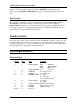
SIGNAL Sound File Format Buffer Attributes All Buffer Types 21 * 22 * 23 * 24 * 25-26 27-28 29 N N N N L L L TPNTS SRATE XLOW XRANGE QTY UNITS SCALE 30-34 35 L L TITLE MODE 36 L WINDOW 37 38-39 N L 40 L SMOOTHING { DATE { Reserved XFSCALE 41-43 44 L I DATE2000 TPNTS 45 N Reserved No. data points (per channel) Sample rate (pts/sec) X-origin (msec) X-range (msec) Physical quantity (e.g. AMPL) Physical units (e.g.
SIGNAL/RTS APPLICATION NOTES Buffer-Type Specific Time & Frequency Buffers 51 52-65 N N ADBITS Reserved A/D resolution [Integer time file only] No. time cells No. frequency cells FFT length Y-origin (Hz) Y-range (Hz) Frequency-Time Buffers 51 * 52 * 53 * 54 * 55 * N N N N N NTIME NFREQ XFTLEN YLOW YRANGE 56-65 N Reserved Buffer Caption 66-85 L CAPTION 80 characters User-Defined Numerical Fields 86 ... 105 N N BVAL1 ...
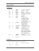
SIGNAL Sound File Format File Header Block #2 User-Defined Label Fields 1-4 ... 37-40 L L BLAB1 ... BLAB10 16 characters 16 characters User-Defined Axis Labels 41-55 56-70 L L XLAB YLAB X-axis label (60 characters) Y-axis label (60 characters) Reserved for System 71-128 N Reserved Format Differences between SIGNAL and RTS SIGNAL and RTS sound files follow the same format, and can generally be interchanged freely.
SIGNAL/RTS APPLICATION NOTES Exchanging Sound Files with External Systems Binary sound files can be exchanged between SIGNAL and other data acquisition systems. This requires that the sound files be in a format compatible with both systems.
Application Note 6 Base Address, IRQ, and DMA Channel Usage Applies to: SIGNAL & RTS NOTE: This note applies only to DT-2821 and DART PCMCIA analog I/O boards. Overview Add-in hardware boards, such as analog I/O, DSP, SCSI controller, etc. are internally set to utilize a particular base address, interrupt level (IRQ), DMA channel, and/or ROM address. Base address sets the address through which the computer communicates with control registers on the board.
SIGNAL/RTS APPLICATION NOTES Base Address, IRQ, and DMA Assignments The following table shows the base address, IRQ, and DMA assignments for the SIGNAL analog I/O and DSP boards and other common system components. If an IRQ or DMA entry is omitted in the table, then that board does not have IRQ or DMA hardware. Note that commercial programs for detecting address, IRQ, and DMA assignments are not reliable.
Application Note 8 Analog I/O Board Diagnostics Applies to: SIGNAL & RTS NOTE: This note applies to DT-2821 analog I/O boards. Introduction If your DT-2821 analog I/O board appears to be malfunctioning, first check your signal source and all cables and instruments leading to or from the I/O board, including the SIGNAL I/O cable and panel. Remove any non-essential components and if possible exchange the others one by one.
SIGNAL/RTS APPLICATION NOTES normal, because the test requires special cabling. All other tests should pass. DIO is not involved in SIGNAL analog I/O operation.
Application Note 10 Digital Transfer between SIGNAL and DAT Recorders Applies to: SIGNAL & RTS NOTE: This note has not been revised for SIGNAL 4.0. Introduction DAT (Digital Audio Tape) recorders store audio signals in digitized format, as a sequence of sampled data points, exactly like a SIGNAL or RTS time buffer. With additional hardware and software, this digitized sound data can transferred directly from the DAT recorder onto the user's hard disk without redigitizing.
SIGNAL/RTS APPLICATION NOTES performance of representative analog and DAT recorders and transfer components. Throughout this note, "RTS" refers to both the RTS and RTSD software programs. Required Hardware and Software Digital sound data is commonly transferred into and out of a DAT recorder via one of several interface standards. AES/EBU is the standard for professional audio, and normally uses 3pin XLR connectors.
Digital Transfer between SIGNAL and DAT Recorders Transfer Software Transfer software controls data flow between the DIO board and computer memory. The digital transfer is performed under Windows, and the DIO board manufacturer normally includes a driver which makes the DIO board look like a conventional Windows sound card.
SIGNAL/RTS APPLICATION NOTES measured by the increase in total harmonic distortion (THD) between the original and resampled signals. Operating Instructions Transferring from DAT to SIGNAL Following is a connection diagram for transferring sound material from the DAT recorder to SIGNAL. Sample rates are shown in ()'s. DAT S/PDIF output DIO board input Sample rate converter Transfer software .WAV file (50 KHz) .WAV file (44.
Digital Transfer between SIGNAL and DAT Recorders Using the DAT File in SIGNAL The Wave file received from the DAT is limited in length only by the recording program and the available disk space. However, SIGNAL time buffers are limited to about 1.2 million data points, or about 27 seconds at 44.1 KHz sample rate. Longer files can be read into SIGNAL in segments using R /W /Q. The Wave file will have the native sample rate of the DAT recorder, either 44.1 KHz or 48 KHz.
SIGNAL/RTS APPLICATION NOTES Transferring from SIGNAL to DAT Following is a connection diagram for transferring sound material from SIGNAL to the DAT recorder. Sample rates are shown in ()'s. SIGNAL buffer (44.1 KHz) SIGNAL buffer (50 KHz) Sample rate converter .WAV file (50 KHz) Transfer software DIO board output .WAV file (44.1 KHz) DAT: S/PDIF input The sounds of interest are stored from SIGNAL buffers as Wave files.
Digital Transfer between SIGNAL and DAT Recorders Performance Specifications DAT Recorders One of the attractions of DAT recorders is their superior performance relative to analog recorders. For interest, following are performance specifications for a few DAT recorders and a studio-quality Studer analog recorder. THD = total harmonic distortion. Values are from manufacturer's specifications except where noted as measured by "(meas)".
Application Note 11 Exchanging Data Files between SIGNAL and MATLAB Applies to: SIGNAL & RTS Introduction The MATLABtm program from The MathWorks (Natick, MA) is a programmable mathematical analysis and display language which provides a broad range of capabilities for mathematical modeling and signal analysis in a language environment similar to SIGNAL's.
SIGNAL/RTS APPLICATION NOTES Transferring Data between SIGNAL and MATLAB Following is a discussion of the SIGNAL and MATLAB commands used to exchange data files between the two programs. Note that SIGNAL files can be stored in two data formats integer or floating point - and two header formats - SIGNAL file header or headerless. See the chapter "File Storage and Exchange" in the SIGNAL User Guide for background.
Exchanging Data Files between SIGNAL and MATLAB 4. Example: read and plot the sample sound file C:\SIGNAL\TWEET.1. To convert and display this file correctly, you must know its conversion format (12-bit A/D) and sample rate (25000 Hz). fid = fopen ('c:\signal\tweet.1','rb'); fseek(fid,1024,'bof'); A = fread (fid,inf,'int16'); A = (A - 2048.) / 204.
SIGNAL/RTS APPLICATION NOTES fid = fopen ('rfile','rb'); fseek(fid,1024,'bof'); A = fread (fid,inf,'float32'); 3. Example: calculate the power spectrum of TWEET.1 in SIGNAL and store it as a SIGNAL-header floating point file, then read and plot this file in MATLAB. To display this file correctly, you must know its FFT length (8192 points) and sample rate (25000 Hz). >R T 1 Filename: C:\SIGNAL\TWEET.1 >XF T 1 1 >W F 1 Filename: TWEET.F In SIGNAL fid = fopen ('tweet.
Exchanging Data Files between SIGNAL and MATLAB Exporting MATLAB floating point time and frequency files to SIGNAL MATLAB values are stored in floating point format, so all MATLAB data is exported as headerless files in 32-bit floating point format. When reading these files, SIGNAL will query the user to establish the time base of the data, since there is no file header to convey this: Buffer type T, F FT Query parameters Sample rate Sample rate, time range, no. time bins 1.
SIGNAL/RTS APPLICATION NOTES 1 5 9 2 6 10 3 7 11 4 8 12 Note that when displaying this matrix numerically, MATLAB will display the first row at the top of the screen, as shown below. However, when displaying the same matrix as a spectrogram, the first row (lowest frequency) will appear at the bottom of the graph. It should not be necessary to rearrange the stored matrix; this is a difference in display conventions.
Exchanging Data Files between SIGNAL and MATLAB 2. In SIGNAL, read the floating point (/F) file RFILE into FT buffer 1. The command queries establish the FT buffer dimensions and time base. >R FT 1 /B /F Sample rate: 25000 Time range (msec): 250 No. time steps: 100 Filename: RFILE Exporting RTS files into MATLAB The RTS writes and reads only time files. It can write either SIGNAL-header or headerless files, but can read only SIGNAL-header files.
SIGNAL/RTS APPLICATION NOTES Issues in Data Storage and Exchange This section provides background on data storage issues that affect data exchange between software systems and hardware platforms. A basic understanding of these issues is important to exchange data accurately and reliably. Text vs. Binary format Data files can be stored and exchanged in either text (ASCII) or binary format.
Exchanging Data Files between SIGNAL and MATLAB Data Precision Another issue in data storage is different precision levels within each numerical format, determined by the number of bytes allocated to store each number in the computer. Obviously, more bytes allow for greater precision and numerical range. Many analysis systems (including SIGNAL) use data lengths of 2 bytes (16 bits) for integer and 4 bytes (32 bits) for floating point, as described above.
SIGNAL/RTS APPLICATION NOTES These formats are used by the following hardware platforms: Little-endian IBM PC VAX DEC Alpha Big-endian Macintosh NexT Sun IBM RS6000 SGi Iris To transfer data into or out of MATLAB to a hardware platform using a different byte-order, use the optional FORMAT parameter in the FOPEN statement to specify the byte-order order of the incoming or outgoing data. MATLAB will then perform byte conversion as necessary.