RAIDER 100 Tube Guitar Amplifier Operator´s Manual Please, first read this manual carefully!
Tube Amp Technology
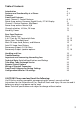
Table of Contents Introduction Features and Functionality at a Glance Contents Front Panel Features: Input; Channel 1 Control Features Power Amp section: Presence, Depth Punch, P.T.M. Display Channel 2 Control Features, Mid Boost Power Amp section: Master A/B Channel selection, Hi Gain, FX Loop Stand By, Power page: 4 4, 5 6 6-8 9 10 10 - 12 12 13 Rear Panel Features: Mains, Mains Fuse S.A.C.
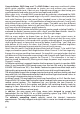
Congratulations, ENGL Amp user! The ENGL Raider is one mean machine of a tubedriven guitar amplifier, engineered to inspire you and enthuse your audience. Alongside to-die-for tone, it puts at your fingertips everything you need to tap your creative potential and make your musical message heard and felt! When yours truly, a humble ENGL amp designer by profession, developed the ENGL Raider 100 amp, two goals loomed large in my mind.
Your ENGL Raider 100 Amp puts at your disposal: 1. a logical control feature array, utmost ease of use and remarkably intuitive handling; 2. Top-drawer sound-shaping options and remarkable versatility: You can combine two channels offering two gain stages each with different midrange voicings for each of these four gain stages. 3.
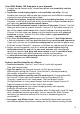
-> The optional Z-9 Custom Footswitch. It lets you select combinations of channels and the two gain stages directly and control two sound-shaping features of your choice. Three ¼” stereo jack plugs accept three dual footswitches that let you control remotely the two channels, the two gain stages, Mid-Boost, Master A/B, FX Loop, and Reverb. -> A Noise Gate for Channel 2. Activate it to suppress excessive noise at very high gain settings.
2 Bright This feature boosts the upper end of the high frequency range for both Channel 1's gain stages, Lo and Hi Gain (or Clean and Crunch modes, if you prefer). Its intensity decreases as gain settings increase. A tip from the designer: For a crisp or glassy tone, activate the Bright boost. It brightens the sound of humbucking or muddy pickups. Bright is a global function; that is, it affects both gain stages.
you set all tone controls to or slightly higher than the center or 12 o'clock position. For higher-gain Crunch sounds, your best bet is to turn the Treble knob down to prevent the pickups and speakers from generating feedback (a setting in the 10-to -1 o'clock range is recommended). Bear in mind that you also have the Bright (2) and the Clean Bright (9) button at your disposal for shaping the high frequency range. 7 Reverb Reverb intensity knob.
11Presence This power amp voicing knob's setting determines the amount of high-end frequencies in Channel 2 (Lead and Hi Gain Lead) in general and for Channel 1 (Clean and Crunch) when the Off / On CH 1 (10) button is engaged or On. 12DepthPunch This power amp voicing knob's setting determines the amount of lo-end frequencies in Channel 2 (Lead and Hi Gain Lead) in general and for Channel 1 (Clean and Crunch) when the Off / On CH 1 (10) button is engaged or On.
measures the current sent to the tube. If it is still too high, the power amp must be checked by a service technician, and the tube may have to be replaced if it is defective. 17 Gain2 Gain control for the Channel 2. This Control knob determines input sensitivity when Channel 2 is active. Use it to dial in the desired amount of preamp saturation level. CAUTION: Extremely high gain and volume levels in Channlel 2 mode can produce powerful feedback.
this volume control is located pre effects loop, it also determines the effects send level for Channel 2. The red LED to the right of the knob lights up to indicate Channel 2 is on. 23 Mid Boost This voicing feature operates globally, affecting both channels by boosting specific midrange frequencies when activated. The LED above the button lights up to indicate Mid Boost is activated. It may also be switched using a Z-9 Custom Footswitch (S.A.C. F1-6 and F2-6, page 26) connected to the S.A.C.
the power amp's volume to two different levels, and then access these volume presets in combination with preamp voicing features such as Mid Boost. The mind boggles… 27 CH 1 / CH 2 This channel switching button selects Channel 1 (Clean or Crunch) or Channel 2 (Lead or Hi Gain Lead) and, depending on the Hi Gain (28) setting, activates Clean, Crunch, Lead, or Hi Gain Lead mode.
Balance is set somewhere between dry and Effect). The FX Loop button enables and bypasses this loop, meaning you can actually activate and deactivate connected effects using a control feature on the amp. The other effects loop, Serial FX Loop, is hardwired into the signal path between the preamp and power amp, and located pre Main FX Loop. If you patch a stomp box or other signal processor into this loop, you must switch this outboard device on to activate its effect and switch it off to bypass it.
33 Mains Fuse Box: The rear chamber contains the mains fuse and in the front chamber, a spare fuse. CAUTION: ALWAYS make sure replacement fuses are of the same type and have the same ratings as the original fuse! Please refer to the fuse ratings table. 34 Footswitch: Serial Amp Control Port (S.A.C.) This serial data input accepts the optional ENGL Z-9 Custom Footswitch, which lets you control various amp functions remotely. Connect the Z-9 Footswitch to the amp using a cord equipped with stereo 6.
Note also: A footswitch may be equipped with LEDs indicating the given switching status. Each of the two switches is provided with approx. 10 milliamperes current, which suffices to power a standard LED. The jack's mono terminal controls Main FX Loop on/off, while the stereo terminal controls Reverb on/off (for pin assignments, see page 24).
gain rigs to generate undesirable peripheral noise in overdriven channels. This is attributable to the physical properties of an amp's constituent components, in particular its active components. That's right; those cherished tubes are the culprits. The Noise Gate is a tool that lets you silence this noise during breaks by way of signal mute circuit. Note that electric guitars pick up interference signals, and these are amplified tremendously at high gain levels in Lead mode.
42 Serial FX Loop Send Connect this output of the Serial FX Loop to a signal processor's input/return jack using the shortest possible shielded cord equipped with 6.3 mm (1/4") plugs. In the signal path, the Serial FX Loop is located post preamp, pre Main FX Loop, and pre power amp and its two Master control knobs. The Serial FX Loop is hardwired into the signal path. If you wish to bypass a connected effect, you must do this on the outboard device by switching it off or hitting its bypass button.
2. An external 8-ohm cabinet and the internal speaker (1x12", 8 ohms) connected to the 4-ohm jacks. When you unplug the cable for the external cabinet, ensure you plug the internal speaker back into a 8-ohm jack! Summary: External 8 Z + internal 8 Z -> external to 4-ohm + internal to 4-ohm output. 3. An external 16-ohm cabinet connected to one of the 8-ohm jacks and the internal speaker (1x12", 8 ohms) connected to one of the 4-ohm jacks.
Handling and Care: * Keep the amp safe from hard knocks and shocks. Tubes are fragile and tend to suffer when exposed to mechanical stress! * Let the amp cool down before you transport it. Ten minutes or so will spare the tubes. * Tubes take some 20 seconds to warm up after you switch the power on, and about two to three minutes before they are able to pump out full power. Make a habit of giving your amp plenty of time to get toasty and flipping the Standby switch for short breaks.
Troubleshooting * Some features that may be controlled remotely using a Z-9 or Z-4 footswitch fail to respond when you change settings: -> Powerful static charges, strong radio signals, or mains voltage spikes can affect microcontroller-driven systems, setting them to an undefined status commonly called a hung chip. In this event, your only choice is to reset the system. Simply switch the amp off and on again.
-> You may be looking at a faulty tube or another defect. In this case, be sure to take the preamp to an authorized, professional service center. * The speaker is emitting humming noises: -> Is there a connection (for example, via a shielded circuit) between the amp and another device that is grounded via a power plug of its own? Two or more circuits sharing a common electrical ground line can cause audible hum. If low-frequency noise is emanating from your rig, be sure to consult a specialist.
Technical Data Output power: Input sensitivity levels Input: Effect Return: Output levels SEND, level range: Power consumption: Fuses: at 230/240 mains voltage at 100/115/120 mains voltage Important: Tubes: V1, V2, V3, V4: V5: V6, V7: V8: Consult Tube Map to view tube array Logic control system: Processor, software: approx. 100 watts; adjusted accordingly to 4, 8 and 16 ohms; from -20 dB nominal, max. 0 dB (CH 1 Lo Gain) from -20 dB nominal, max. 0 dB nominal -20 dB to approx. max. dB approx.
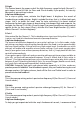
Tube Map: cooling fan connector output transformer power V4 transformer V8 46 electrolytic capacitor: anode supply smoothing V3 V2 V7 V1 V6 reverb main connector: red plug -> reverb spring input black plug -> reverb spring output V5 amp chassis as viewed from above; Front panel, Input the tubes and their function: V 5 - ECC83 (12AX7): input stage, 2. stage; grade: FQ selected V 6 - ECC83 (12AX7): Lead driver stage, 4.
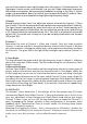
Your Options for controlling the ENGL Raider 100 amp remotely: S.A.C. Port Footswitch Noise Gate Main FX Loop Serial FX Loop CAUTION ! R Tube DO NOT OPEN ! RISK OF ELECTRIC SHOCK ! DO NOT EXPOSE THIS EQUIPMENT TO R AIN OR MOISTURE ! Amp Serial Amp FX Loop Control Port Reverb CAUTION: Connect Custom Footswitch Z-9 Only! Master A/B Mid Boost CH 1 / CH 2 Hi Gain Off max.
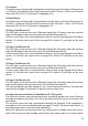
Noting Settings: Gain 1 Tube Bass Middle Treble Reverb Volume 1 Presence Depth Punch RAIDER 100 Clean off / on Bright CH 1 Bright V1 V2 V3 V4 Power Tube Monitor Amp Gain 2 Input Bass Middle Treble Reverb Volume 2 Master A Master B Mid Master Boost A/B CH 1 CH 2 Hi Gain FX Loop Stand By Power Sound title: _ _ _ _ _ _ _ _ _ _ _ _ _ _ _ _ _ _ _ _ comment: _ _ _ _ _ _ _ _ _ _ _ _ _ _ _ _ _ _ _ _ _ _ _ _ _ _ _ _ _ _ _ _ _ _ _ _ _ Gain 1 Tube Bass Middle Treble Reverb Volume
Configuration table for assigning the Raider 100's sound-shaping and special functions to the Z-9 Custom Footswitch's Functions 1 and 2 : Button Function 1 Function 1 Function 1 Function 1 Function 1 Function 1 Function 1 Function 1 Function 2 Function 2 Function 2 Function 2 Function 2 Function 2 Function 2 Function 2 Functions Raider amp Master A/B no Main FX Loop off / on Reverb off / on no Mid Boost no no no no no Reverb off / on no Mid Boost Main FX Loop off / on no Setup 1: Channel 1 1: Channel 2 1:
page: >6< 1 Tube <---------------------------------------- 7 ----------------------------------------> <-------------------- 8 --------------------> 2 3 4 5 6 7 8 Gain 1 Bass Middle Treble Reverb Volume 1 9 <------------------------- 9 ------------------------> 10 11 12 Presence Depth Punch RAIDER 100 Clean off / on Bright CH 1 Bright 13 14 15 16 V1 V2 V3 V4 Power Tube Monitor Amp Gain 2 Input Bass Middle Treble Reverb Volume 2 Master A Master B Mid Master Boost
R Tube Amp Technology Gerätebau GmbH Germany Internet: http://www.engl-amps.