
Operator`s manual

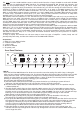
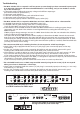

3 SWITCH LOOP 1
Press this button to determine Switch Loop 1's status. This circuit is wired to a stereo 1/4“ jack (12).
The red LED above the button indicates the status:
LED off => Switch Loop 1 is an open circuit, which deactivates function* 1.
LED on => Switch Loop 1 is a closed circuit, which activates function* 1.
Changing Loop 1's status also triggers an S.A.C. message in serial data format that is sent to the
S.A.C. Out (15) port. For Loop 1 this S.A.C. command lets you control a given ENGL amp function – for
example Channel Up/Down on the Powerball-2 – directly via the S.A.C. port.
4 SWITCH LOOP 2
Press this button to determine Switch Loop 2's status. This circuit is wired to a stereo 1/4“ jack (12).
The red LED above the button indicates the status:
LED off => Switch Loop 2 is an open circuit, which deactivates function* 2.
LED on => Switch Loop 2 is a closed circuit, which activates function* 2.
Changing Loop 2's status also triggers an S.A.C. message in serial data format that is sent to the
S.A.C. Out (15) port. For Loop 2 this S.A.C. command lets you control a given ENGL amp function – for
example Channel 1/2 - 3/4 on the Powerball-2 – directly via the S.A.C. port.
5 SWITCH LOOP 3
Press this button to determine Switch Loop 3's status. This circuit is wired to a stereo 1/4“ jack (13).
The red LED above the button indicates the status:
LED off => Switch Loop 3 is an open circuit, which deactivates function* 3.
LED on => Switch Loop 3 is a closed circuit, which activates function* 3.
Changing Loop 3's status also triggers an S.A.C. message in serial data format that is sent to the
S.A.C. Out (15) port. For Loop 3 this S.A.C. command lets you control a given ENGL amp function – for
example Master A/B on the Powerball-2 – directly via the S.A.C. port.
6 SWITCH LOOP 4
Press this button to determine Switch Loop 4's status. This circuit is wired to a stereo 1/4“ jack (13).
The red LED above the button indicates the status:
LED off => Switch Loop 4 is an open circuit, which deactivates function* 4.
LED on => Switch Loop 4 is a closed circuit, which activates function* 4.
Changing Loop 4's status also triggers an S.A.C. message in serial data format that is sent to the
S.A.C. Out (15) port. For Loop 4 this S.A.C. command lets you control a given ENGL amp function – for
example Middle-boosted on the Powerball-2 – directly via the S.A.C. port.
7 SWITCH LOOP 5
Press this button to determine Switch Loop 5's status. This circuit is wired to a stereo 1/4“ jack (14).
The red LED above the button indicates the status:
LED off => Switch Loop 5 is an open circuit, which deactivates function* 5.
LED on => Switch Loop 5 is a closed circuit, which activates function* 5.
Changing Loop 5's status also triggers an S.A.C. message in serial data format that is sent to the
S.A.C. Out (15) port. For Loop 5 this S.A.C. command lets you control a given ENGL amp function – for
example FX Loop Off/On on the Powerball-2 – directly via the S.A.C. port.
8 SWITCH LOOP 6
Press this button to determine Switch Loop 6's status. This circuit is wired to a stereo 1/4“ jack (14).
The red LED above the button indicates the status:
LED off => Switch Loop 6 is an open circuit, which deactivates function* 6.
LED on => Switch Loop 6 is a closed circuit, which activates function* 6.
Changing Loop 6's status also triggers an S.A.C. message in serial data format that is sent to the
S.A.C. Out (15) port. For Loop 6 this S.A.C. command lets you control a given ENGL amp function – for
example noise Gate Off/On on the Powerball-2 – directly via the S.A.C. port.
* This is the amp function controlled via the given loop. A function is normally activated by closing
a switch loop circuit.
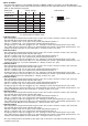
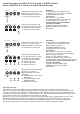
2 MIDI CHANNEL
Use these DIP switches to set the MIDI channels to OMNI or POLY 1 through 8 to enable MIDI data
reception. The table below shows the DIP switch settings for the respective channels. You'll find the same
table on the Switcher's top panel.
MIDI Data Switch settings code switches:
reception via 1 2 3 4
OMNI-Mode up x x x
POLY Channel 1 down up up up
POLY Channel 2 down up up down
POLY Channel 3 down up down up
POLY Channel 4 down up down down
POLY Channel 5 down down up up
POLY Channel 6 down down up down
POLY Channel 7 down down down up
POLY Channel 8 down down down down
x => setting does not affect mode
1234
up
down