
Operator`s manual

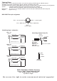
Setup and Installation:
You have several setup and installation options:
1. To set the Switcher on a flat surface, first stick the four adhesive rubber pads to the bottom of the device.
2. Attach it to your ENGL device using the velcro strips, for instance, to the Powerball's rear panel or inside
the speaker cabinet area of a combo's housing.
3. To install it in a 19" rack, attach the optional rack-mount panel to the Switcher's front face using four screws.
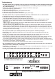
Connections:
1. CAUTION: Make sure the amp and Switcher are both off when you connect the two.
2. Use conventional cables equipped with stereo 1/4“ jack plugs to connect the Switcher and amp. If necessary,
you can use a Y adapter to split a stereo plug and access the two switch loops via two mono plugs. Always
choose the shortest possible cord to connect the Switcher's S.A.C. Out to the amp's S.A.C. port.
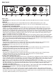
3. Use a standard cord with 5-pin connectors to connect a MIDI footswitch such as an ENGL Z-9, Z-12 or Z-15
MIDI Footcontroller or other MIDI-enabled device to the MIDI IN port (10). Use a MIDI cable to connect
other MIDI devices such as signal processors and the like to the MIDI-THRU port.
4. Heads up: Never bend cords at excessive angles anywhere near the plugs inserted in the amp and Switcher.
Make sure nothing pulls on or otherwise exerts undue force on the connectors. The same goes for
MIDI cables.
Operating the Switcher and other practical tips:
Once you have plugged in all the necessary cords, first check the switch loops' allocations to the amp's various
functions. You can do this after powering the amp and the Switcher up, without first selecting a MIDI memory
slot. The switches or buttons controlling Channel, Clean/Lead, and similar functions on ENGL amps are
deactivated as soon as a 1/4" plug is inserted in the corresponding jack. Be sure to use a stereo 1/4"plug for
stereo 1/4“ jacks because all jacks control two functions and using a mono plug would disable the second
function.
Here's a helpful tip: Make labels designating amp switching functions such as Clean/Lead, High Gain, and so
forth, and stick each near the corresponding button on the Switcher before you start programming individual
MIDI memory slots. If you plan to frequently tear down and set up your rig elsewhere, you may want to use
different colored cables or another color code of your own devising to mark the connections between the amp
and Switcher. Stick a piece of tape of the same color to the jacks and ports on both devices or number the
cords and jacks to avoid confusion when you set your rig up again. This will spare you headaches once you
have finished programming, because malfunctions are guaranteed if switch loops are incorrectly allocated to
amp functions.
You have another remote-control option for ENGL amps alongside the six switch loops: Simply connect your
ENGL amp that is equipped with a S.A.C. Port to the S.A.C. Out (15) port to send MIDI messages via the S.A.C.
interface. This lets you do things like switch two ENGL Powerball-2 amps or an early Powerball version and a
later Powerball-2 version in parallel via MIDI. The six switch loops serve to control amp #1, while amp #2 is
switched via the S.A.C. Out. The switch loops and S.A.C. Out's ground circuits are split inside the Z11 Switcher,
thereby preventing hum caused by control circuit ground loops. Of course, you are free to control one ENGL
amp that is equipped with a S.A.C. Port via the S.A.C. Out without configuring switch loops for a second amp.
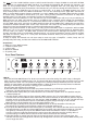
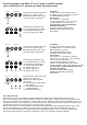
Programming and storing switch loop configurations to MIDI memory slots:
1. Select a MIDI memory slot using a MIDI footcontroller such as the ENGL Z-9, Z-12 or Z-15.
2. Use buttons (3) through (8), (depending on the employed switch loops) to configure
amp functions, for example, Channel selection, Master A or B, Mid Boost off/ on,
FX Loop off / on, and so forth.
3. Press and hold the WRITE button (1) for about one second. The brief delay serves to prevent
accidental programming or deleting.
4. The Status LED lights up briefly to indicate the program is being saved.
5. Repeat steps 1 to 4 to program further MIDI memory slots.
6. Follow the same procedure to edit any previously stored MIDI patch.
Note: The status LED flashes slowly when you edit switch loop settings. It will do this only after you have
selected a MIDI Preset via a MIDI footcontroller.