
Operator`s manual


* The MIDI Switcher fails to respond. It will not power up even though you have connected its power pack
to an AC outlet. The Status LED above the WRITE button is not flashing, and you are unable to activate
any of the switch loops.
-> Is the power pack providing the necessary voltage and sufficient amperage?
(See Technical Data for specifications.)
-> Is the power pack defective?
-> Is the cord connecting the power pack and Switcher intact?
-> Is the power pack connected to a live socket?
-> Is the connector properly seated in the Power Supply socket (16)?
* The MIDI Switcher fails to respond to MIDI data sent from a MIDI device such as a footcontroller.
-> Is the MIDI footcontroller connected to the MIDI In port (15)?
-> Is the MIDI cable in good working order and is it wired properly?
(You'll find the MIDI connector's wiring pictured on the last page.)
-> Is the Switcher set to the MIDI channel on which the MIDI footcontroller is sending program change
commands? You can check if the Switcher is receiving MIDI data by setting the DIP switch (2) to
OMNI reception.
If MIDI program change messages are sent via a MIDI channel other than the one selected at the Switcher,
it will not switch to the target memory slot.
The Status LED above the WRITE button flashes rapidly to indicate that the MIDI channels do not match.
Now if you press the WRITE button, the Status LED will light up constantly until you release the button to
indicate that your setting cannot be stored because the target memory slot cannot be addressed. In other
words, a flashing LED tells you what is causing the communication problem; a statically illuminated LED tells
you why you cannot store a setting.
* The remote-controlled amp's switching functions do not respond to switch loop changes.
-> Check if the cord(s) equipped with the stereo 1/4“ jack plugs is/are connected properly to the amp
and Switcher.
-> Are the 1/4“ jack plugs on the cords connecting the Switcher and amp wired in stereo and in good
working order? Check them for broken wires, bad solder joints, and short-circuits.
-> If the Switcher is unable to address an amp via the switch loops, the wiring on this amp's stereo 1/4“ jacks
may not match the wiring of the jacks on the opposite end; that is, the switcher's control inputs.
If you need to check the wiring, you'll find the scheme for the 1/4“ stereo jacks pictured on the last page.
-> If you are dealing with an amp other than ENGL, is it designed to respond to a simple on/off electrical circuit
controlled by a single-pole, single-throw switch?
If you are unsure, contact your local authorized service center or consult a professional.
* The switchable functions on an ENGL amp controlled remotely using the S.A.C. Out (15) do not respond
when you activate or deactivate a switch loop.
-> Check if the cord equipped with the stereo 1/4“ jack plugs is connected properly to the amp (-> S.A.C. Port)
and Switcher (-> S.A.C. Out).
-> Are the 1/4“ jack plugs on the cords connecting the Switcher and amp wired in stereo and in good
working order? Check them for broken wires, bad solder joints, and short-circuits.
Troubleshooting
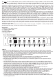
WRITE
MIDI
CHANNEL
SWITCH
LOOP 1
SWITCH
LOOP 2
SWITCH
LOOP 3
SWITCH
LOOP 4
SWITCH
LOOP 5
SWITCH
LOOP 6
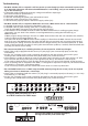
MIDI SWITCHER
MIDI THRU MIDI IN
LOOP 1 & 2
COM. L2 L1
S
ERIAL
A
MP
C
ONTROL
O
UT
(S.A.C.)
MIDI SWITCHER / TYPE: Z-11-S.A.C.
POWER
SUPPLY
MIDI
FOOTCONTROLLER
Z-12
x
LOOP 3 & 4
COM. L4 L3
7-14 Volts AC
9-20 Volts DC
300 mA
LOOP 5 & 6
COM. L6 L5
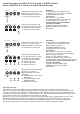
Using the MIDI Switcher Z11-S.A.C.
as a MIDI interface for ENGL amps:
See the next page for practical examples,
wiring instructions, and useful tips.
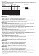
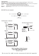
Lead (3)
Bottom
Lead Gain-3
Clean Gain-1
Lead (4)
Bottom
Bright Bottom
Bass
Bass
Middle
Middle
Middle-boosted
Treble-Clean
Treble
Treble-Crunch
Lead Vol.-3
Clean Vol.-1 Crunch Vol.-2
Lead Vol.-4 Master A
Presence
Master B
Depth Punch
Power
Stand By
Lead Gain-4
Crunch Gain-2
Input
Channel
1 / 2
3 / 4
Channel
Up /
Down
Middle-
boosted
Power Tube Monitor
V1 V2 V3 V4
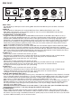
Amp
Tube
Powerball
II
REPLACE FUSE
ONLY WITH SAME TYPE
AND RATING !
DO NOT OPEN !
RISK OF ELECTRIC SHOCK !
DO NOT EXPOSE THIS EQUIPMENT
TO RAIN OR MOISTURE !
CAUTION !
!
FX Loop
Send Return Balance
Dry Effect
100 W All-tube Guitar Amp Head
Powerball-2
T
YPE
E645-2
designed by Horst Langer
MADE IN GERMANY
Poweramp Output
48
Or
8
And Or->
8 Ohms Parallel
1 x 8 Ohms
2 x 16 Ohms
4 Ohms Parallel
1 x 4 Ohms
2 x 8 Ohms
16 Ohms
Threshold
Off-Lo Hi
Noise Gate
Lead Channel
Serial Amp
Control Port
CAUTION:
Connect Custom
Footswitch Z-9 Only!
Channel
Up
/
Down
1
/
2 - 3
/
4
Footswitch
Master A
/
B
Middle-
boosted
FX Loop-
off
/
on
Noise Gate
S.A.C. Port
8
16
Or
16
And
16
Or->
R
Amp
Tube