EVOLUTION PELLET STOVE INSTALLATION & OPERATION MANUAL 25-EP 55-SHPEP 55-TRPEP Rev. 8/2008 CAUTION Please read this entire manual before installation and use of this pellet fuelburning appliance. Keep children, furniture, fixtures and all combustibles away from any heating appliance. SAFETY NOTICE Failure to follow these instructions can result in property damage, bodily injury or even death. For your safety and protection, follow the installation instructions outlined in this manual.
IMPORTANT: IF YOU HAVE A PROBLEM WITH THIS UNIT, DO NOT RETURN IT TO THE DEALER. CONTACT TECHNICAL SUPPORT @ 1-800-245-6489 Mobile Home Use: This freestanding pellet unit is approved for mobile home or doublewide installation with the outside combustion air hookup. See the “Installation” section of this manual for details pertaining to mobile home installations. Mobile home installation must be in accordance with the Manufactured Home and Safety Standard (HUD), CFR 3280, Part 24.
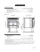
TABLE OF CONTENTS Introduction • Introduction...................................4 Specifications • • • • Heating Specifications ..................5 Dimensions ...................................5 EPA Compliance...........................5 • Installation • • • • • • • • • Installation Overview....................6 Clearances to Combustibles..........7 Venting Introduction.....................8 Venting Guidelines .......................8 Additional Venting Information ...
INTRODUCTION Thank you for purchasing this fine product from England’s Stove Works! England’s Stove Works was started, and is still owned by, a family that believes strongly in a “Do It Yourself” spirit; that’s one reason you found this product at your favorite “Do It Yourself” store. We intentionally design and build our stoves so that any homeowner can maintain their unit with basic tools, and we’re always more than happy to show you how to do the job as easily and as inexpensively as possible.
SPECIFICATIONS Heating Specifications • • • • • Heat Output Range**............................................10,700 BTU/hr – 25,100 BTU/hr Approximate Pellet Burn Rate** ............................................... 1.6 lb/hr – 3.9 lb/hr Maximum Burn Time** ..............................................................................40 hours Approximate Square Footage Heated*** ...................................... 800 - 2000 sq. ft. Hopper Capacity ...................................................
INSTALLATION Installation Overview When choosing a location for your new stove, there are a multitude of factors that should be taken into account before beginning the installation. 1. Traffic Patterns – To help prevent accidents, the stove should be placed in a location where it is out of the way of normal travel through the home. 2. Heat Flow – When deciding on a location for the stove, consider the way heat moves throughout your home.
INSTALLATION Clearances to Combustibles Unit Clearances to Combustibles Side ( A ) 6 IN. 152.4 MM. • • • • • • • • • • Rear ( B ) 6 IN. 152.4 MM. Corner ( D ) 4.5 IN. 114.3 MM. Min. Alcove Height 51 IN. 1295.4 MM. Min. Alcove Width 38 IN. 965.2 MM. WARNING INSTALL VENT AT CLEARANCES SPECIFIED BY THE VENT MANUFACTURER. HOT! Do not touch! Severe burns or clothing ignition may result. Glass and other surfaces are hot during operation. CAUTION Keep children away.
INSTALLATION Venting Introduction This pellet stove operates on a negative draft system, which pulls combustion air through the burn pot and pushes the exhaust air to the vent pipe and out of the building. This unit must be installed in accordance with the following detailed descriptions of venting techniques; not installing the stove in accordance with the details listed here can result in poor stove performance, property damage, bodily injury or death.
INSTALLATION Additional Venting Information • Do not mix and match components from different pipe manufacturers when assembling your venting system (i.e. Do NOT use venting pipe from one manufacturer and a thimble from another). • We require a minimum vertical rise of 36 in. (3 ft.) of pipe to create natural draft in the system, which helps evacuate smoke from the stove in the event of a power failure or combustion blower failure. • Venting systems 15.0 ft. or shorter may be composed entirely of 3.0 in.
INSTALLATION Approved Venting Method 1: Through the Wall • Generally the simplest installation method, venting through the wall using our AC-3000 kit (or similar venting system) is also the preferred venting method. It minimizes horizontal pipe, allows the stove to be installed close to the wall and keeps the clean-out tee on the outside of the house, for ease of cleaning.
INSTALLATION Approved Venting Method 2: Through the Ceiling • Venting through the ceiling/roof may be the only feasible venting option in some cases and is a factory recommended installation. • When installing any venting system, Type L or Type PL pipe must be used and all clearances to combustibles listed by the pipe manufacturer must be strictly adhered to.
INSTALLATION Approved Venting Method 3: Existing Chimney System • Using an existing masonry or factory built chimney for venting is the only other acceptable method for venting this pellet unit. • Use Type L or Type PL venting pipe until entering the existing chimney. Use the appropriately sized adapter when transitioning from the pellet vent pipe to the masonry or factory built thimble and be certain that the adapter is sealed tightly to both the pellet venting system and the existing chimney.
INSTALLATION Mobile Home Installation • As with all installations involving this unit, the use of outside combustion air is mandatory and MUST be used. Please see the “Outside Air” section on page 14 for more information regarding outside air connections. • The pellet stove MUST be secured to the floor of the mobile home using lag bolts and the holes provided in the bottom of the pedestal for this purpose.
OUTSIDE AIR HOOK-UP • The use of outside combustion air is mandatory on the 25-EP. • The outside air connection pipe protrudes from the lower rear center of the stove; use the included outside air kit to attach your stove to outside combustion air. Instructions and all the parts needed to make the outside air connection to your pellet stove are included with the outside air kit.
FLOOR PROTECTION • The 25-EP requires a non-combustible floor protector if the stove is to be installed on a combustible floor. If the floor the stove is be installed on is already non-combustible (i.e. a concrete floor in a basement), no floor protection is needed (although a decorative floor protector can still be used for aesthetic reasons).
DAILY OPERATION Getting Started • Check to see that the hopper is clean and free from foreign materials. Be sure to connect this unit to a working outlet; we recommend using a surge protector to help protect the electronic components from damage. • BEFORE your first fire, dry run your unit (no pellet fuel in the hopper) for twenty minutes; pressing the “ON” button with the unit plugged in will initiate the dry run.
• The 25-EP will perform equally well using softwood and hardwood pellets, and although the ash may differ slightly in appearance or texture, both types of pellets will burn cleanly and efficiently in this stove. • The 25-EP is equipped with an automatic pellet ignition system; the only user input required to light the stove is a simple press of the “On” button. • Shortly after pressing the “On” button, the letters “S U” will appear in the heat range and blower speed windows of the control board.
CONTROL BOARD SETTINGS The control board on this stove allows the user to adjust the heat output and convection blower speed, turn the unit on and off, and test components for function (more on diagnostic mode later). • The lower buttons on the control board (Low Fuel Feed, Low Burn Air, and Air on Temp) are not meant to be adjusted during normal operation of the unit. These buttons are factory preset and should not be adjusted by the user. • To energize the unit and initiate a fire, press the “On” button.
ERROR CODES Error codes, or “E-Codes,” are alphanumeric codes that will appear in the Heat Range and Blower Speed windows of the Control Board if the unit experiences an abnormal condition. Error codes are the control board’s way of telling the user that something isn’t operating correctly within the stove, and that the unit should be carefully inspected before reigniting. See the “Trouble-Shooting Guide,” page 36, for additional information on error codes.
POWER FAILURE If the power to the unit is interrupted for approximately three minutes or less, the unit will resume operation when power is restored according to the following table: Unit’s State Before Power Loss State When Power Returns ON Start-Up Start-Up Start-Up Shut-Down Shut-Down OFF OFF ¾ If the power is interrupted for more than (approximately) three minutes, the unit will be “OFF” when power returns. ¾ IMPORTANT – Do NOT open the hopper lid or the door to the unit during power outage.
THERMOSTAT OPERATION Thermostat Installation 1. Unplug the unit and remove the back panel of the stove. 2. Locate the thermostat connect block, labeled J18, on the rear of the control board, near the bottom (See image below and pg. 43 of this manual for a control board diagram). It will have a small wire “jumper” installed in it from the factory. This jumper bypasses the thermostat and should be saved. 3. Loosen the two screws using a small slotted “jewelers” screwdriver and remove the “jumper.” 4.
THERMOSTAT OPERATION Thermostat Operation Details • The 25-EP was designed to operate equally well in both manual and thermostat mode. While using the control board for heating control gives the user control over the heat output of the stove, the thermostat allows the stove to “start-up” and “shutdown” independently which will help maintain your house at a more constant temperature and save pellet fuel.
DAILY MAINTENANCE Important Notes • As with any maintenance concerning this unit, be sure the unit is “OFF” and has completed the Shut-Down cycle BEFORE beginning. • Be aware that metal parts in the firebox can remain HOT long after the fire has gone out and EVEN after the Shut-Down cycle is complete. Always use extreme caution when handling potentially hot stove parts, even if you think they should be cold.
DAILY MAINTENANCE Ash Removal and Disposal • Press the “Off” button and allow the stove to complete the shut-down cycle and cool completely. • Grasp the heat exchange cleaning rod located at the middle of the decorative room air grill and repeatedly pull it in and out until ash stops falling from the tubes into the firebox. NOTE – The heat exchange tubes are the primary medium which transfers heat from the fire into the room. Keeping them free of fly ash is crucial to high efficiency operation of the unit.
DAILY MAINTENANCE Cleaning the Burnpot Along with removing ashes from the stove, cleaning the burnpot is the other essential part of daily maintenance that will keep the stove operating at its peak. Pellets contain varying amounts of impurities and fusible material that will accumulate in the burnpot over time. Some pellets will contain much higher amounts of these fusible impurities, therefore extra vigilance may be required to maintain a clean burnpot.
BIWEEKLY MAINTENANCE Important Notes • As with any maintenance concerning this unit, be sure the unit is “OFF,” has completed the Shut-Down cycle, and is completely cool BEFORE beginning. • Be aware that metal parts in the firebox can remain HOT long after the fire has gone out and EVEN after the Shut-Down cycle is complete. Always use extreme caution when handling potentially hot stove parts, even if you think they should be cold.
BIWEEKLY MAINTENANCE Baffle Removal • Using the integral tube cleaner, as mentioned in the Daily Maintenance section, helps to keep the heat exchanger tubes free from fly ash; however, fly ash will still accumulate on the baffle shelf and in other non-visible areas. • The firebox baffle is a free floating design, which reduces thermal stresses on the baffle and makes it easily removable for cleaning. • Remove the baffle by: o Grasping the baffle lifting tab in the center of the baffle.
MONTHLY MAINTENANCE Important Notes • As with any maintenance concerning this unit, be sure the unit is “OFF,” has completed the Shut-Down cycle, and is completely cool BEFORE beginning. • Be aware that metal parts in the firebox can remain HOT long after the fire has gone out and EVEN after the Shut-Down cycle is complete. Always use extreme caution when handling potentially hot stove parts, even if you think they should be cold.
MONTHLY MAINTENANCE Exhaust Chamber Cleaning The exhaust chamber of the stove was intentionally designed as an ash accumulation area. Allowing ash to accumulate here prevents excess ash build-up in the combustion blower and the venting system. Similarly, the exhaust chamber is easily accessible via the two exhaust chamber clean-out ports located in the firebox.
• MONTHLY MAINTENANCE Venting Pipe Cleaning • Low spots and direction changes in the venting system (such as tee’s and elbows) are areas for potential fly-ash accumulation. INSPECT these areas diligently to keep the venting system in safe operating condition. • Depending on the specific type of venting system your stove is connected to, it may be possible to remove the clean-out tee cover and simply run a pipe brush up the pipe to remove any fly-ash accumulation.
• YEARLY MAINTENANCE Important Notes • As with any maintenance concerning this unit, be sure the unit is “OFF,” has completed the Shut-Down cycle, and is completely cool BEFORE beginning. • Be aware that metal parts in the firebox can remain HOT long after the fire has gone out and EVEN after the Shut-Down cycle is complete. Always use extreme caution when handling potentially hot stove parts, even if you think they should be cold.
YEARLY MAINTENANCE Exhaust Blower Cleaning Although the exhaust blower and blower housing were designed to minimize ash build-up, some fly-ash will still accumulate there throughout the burning season. The amount and type of ash will depend on the type of pellets and venting system, but generally this accumulation will be mild.
• Loosen the five (5) 5/16” self-drilling screws which hold the exhaust blower to the exhaust blower tube. The lower screws are most easily accessed through the circular cutouts in the stove body. A 12” socket extension will likely be necessary to reach all of the screws. • Lift the exhaust blower up and out of the stove. The gasket which seals the exhaust blower to the exhaust blower tube is fragile, so take extra care when removing the blower.
• YEARLY MAINTENANCE Convection Blower Cleaning As always, be certain the stove is cool and unplugged before servicing any components within the unit. Since the convection blower does not handle any byproducts of combustion, it does not require serious cleaning like the exhaust blower. However, dust from the home and other debris in the air can accumulate on the blades of the convection blower.
• YEARLY MAINTENANCE Checking Gaskets An airtight seal at the door openings and hopper lid opening is crucial to proper stove performance. Any air leaks at these areas can not only cause a dirty, inefficient burn but can also pose a serious safety threat. Because of this, gaskets should always be maintained in good condition. Gasket tightness can be checked using the “dollar-bill” method: ∗ Place a dollar bill between the gasket and the stove body (at the location where the gasket meets the stove).
TroubleShooting Guide WARNING: To avoid ELECTRICAL SHOCK always disconnect the unit from the power source BEFORE attempting any repair. If this guide does not correct the problem, call your local dealer or Technical Support at 1‐800‐245‐6489. Problem Auger not turning Smoke smell or dust in house Room blower not operating Cause 1. Bad auger motor. 2. Foreign matter jamming auger. 3. Vacuum sensor. 1. Improper exhaust connection. 1. Loose thermal sensor. 2.
"E‐1" Code On Control Board Unit Shuts Down in 15‐20 minutes with an "E‐2" code on control board. "E‐3" Code on Control Board (Overfire) "E‐4" Code on Control Board (Proof of flame lost) 2. Loose exhaust fan set screw. 1. Vacuum bypass chip missing. 1. Loose thermal sensor. 2. Check set screw for tightness. 1. Contact Technical Support. 1. Check both sides of thermal sensor connection (exhaust blower and control board). 2. Control board settings. 2.
REPLACING COMPONENTS Auger Motor 1. Before beginning any component replacement, be certain the unit is unplugged and thoroughly cooled down. Also, make sure the hopper is empty before attempting to remove or replace the auger motor assembly. 2. Remove the side panels and back panels as previously detailed in this manual on Page 32 in the “Exhaust Blower Cleaning” section. Before loosening any bolts, detach the wiring harness from the auger motor. 3.
REPLACING COMPONENTS Convection Blower Combustion Blower 1. Before beginning any component replacement, be certain the unit is unplugged and thoroughly cooled down. 1. Before beginning any component replacement, be certain the unit is unplugged and thoroughly cooled down. 2. Remove the right side panel as previously detailed in this manual on Page. 32 in the “Exhaust Blower Cleaning” section. 2. Remove the left side panel as previously detailed on pg. 32. 3.
REPLACING COMPONENTS Vacuum Switch Igniter 1. Before beginning any component replacement, be certain the unit is unplugged and thoroughly cooled down. 1. Before beginning any component replacement, be certain the unit is unplugged and thoroughly cooled down. 2. Remove the right side panel and the back panel as previously detailed. 2. Remove the right side panel and the back panel as previously detailed. 3. Locate the vacuum sensor as shown in the diagram below. 3.
REPLACING COMPONENTS IMPROPER GASKET MAINTENANCE, INCLUDING FAILURE TO REPLACE GASKETS, CAN CAUSE AIR LEAKS RESULTING IN SMOKE-BACKS. Gaskets 1. Door o This unit comes with a 1/2” rope gasket around the door that should be replaced at least every two years. To replace the door gasket (Part # PU-DGK), the old gasket must first be removed entirely — prior to adding the new adhesive, you may have to scrape the old cement from the door channel.
REPLACING COMPONENTS Control Board The Control Board (Part # PU-CBEP) is a digital read-out board. This board offers a wide variety of settings to operate the unit. The right side panel should be removed prior to removing the control board. The control board can be removed from the unit by loosening the two outside screws and pulling the board back to the inside of the stove. A 6-amp “quick-blow” fuse is used on this Control Board.
WIRING DIAGRAM PU-CBEP Control Board Diagram Caution – Shock Hazard • Press the “Off” button and let the appliance completely cool BEFORE unplugging the appliance and beginning any maintenance or component replacement. • Risk of shock if appliance is not unplugged before service.
OPTIONAL ACCESSORIES Wall Thermostat (GU-1E30-914) Installing this wall thermostat allows the 25-EP to operate on the same principle as a furnace: The stove will shut-down and relight as the call for heat comes and goes. This will maintain the house at a more constant temperature, while conserving pellets. Remote Thermostat (AC-3001) The remote thermostat for the 25-EP takes the convenience of thermostat operation one step further by allowing temperature adjustments from anywhere in the home.
ILLUSTRATED PARTS DIAGRAM Auger Motor Assembly Steel Door Assembly Page | 45
REPLACEMENT PARTS LIST Part Number Part Description Diagram # Hopper Lid Gasket Door Gasket Three Piece Window Gasket Kit Exhaust Blower Gasket Ash Pan Gasket Cradle Mating Gasket 1 2 3 4 5 6 Igniter Cartridge Heater Exhaust Blower Room Air Blower Hopper Lid Switch .
LIMITED FIVE (5) YEAR WARRANTY From the date of purchase to the original owner The manufacturer extends the following warranties: Five Year Period: 1. Carbon steel and welded seams in the firebox are covered for five (5) years against splitting. 2. The steel door and hinges are covered for five (5) years against cracking. One Year Period: 1.
Procedure Purchaser must give notice of claim of defect within the warranty period and pay transportation to and from a service center designated by the manufacturer. The dealer from which the unit was purchased or the factory, at our option, will perform the warranty service. Other Rights This warranty gives you specific legal rights; you may also have other rights, which may vary from state to state.
WARRANTY REGISTRATION for England’s Stove Works® Purchaser Information I. Purchased By (Name) _________________________________________ II. Address ____________________________________________________ III. City_______________________State________Zip Code ____________ IV. Telephone Number ___________________________________________ V. Email Address _______________________________________________ Dealer Information VI. Purchased From _____________________________________________ VII.
Important Notice This registration information MUST be on file for this warranty to be valid. Please mail this information within thirty (30) days from the original date of purchase. Use any of these three easy ways to send your warranty information in! Mailing Address England’s Stove Works, Inc. Technical support Department P.O. Box 206 Monroe, Virginia 24574 Fax Number (434) 929-4810 – Twenty-four hours a day. Online Registration Visit our warranty registration website at: http://www.englanderstoves.