EN-898X USER MANUAL 1. Introduction…………………………………………….2 2. Specification………………..…………………………..6 3. Setup 3-1. Installing the server board………………………….7 3-2. Adding components to the server board……12 3-3. Reattaching the cover…………………………..12 3-4. Installing optional peripherals and devices Hard Drives………………………………………….13 CD-ROM/FDD………………………………………..16 Power Supply………………………………………..17 Fan……………………………………………………..18 PCI Slot……………………………………………………22 3-5. Installing 2U in the cabinet……………………..25 4.
Introduction The EN-898X 2U Rackmount Chassis is a brand new product from Enlight Corporation. It provides the perfect solution for users who need a compact 2U rackmount server chassis. The En-898X series is an ISP’s 2U workhouse perfect for caching, proxy, DNS, Firewall, application. With 4x 3.5'' (8982: 6×3.5''/ 8983: 9x 3.5'') one inch hard disk in tray and slim CD-ROM and standard floppy disk drive bay,5.25'' drive bay; you can stack the 2U units inastandard19''rackcabinet.
8981 3
8982 4
8983 notice: this pictures are just for reference.
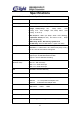
Specifications EN-898X Rackmount Chassis Specifications Mainboard for factor follow SSI & ATX 12” x 13” specification Power Supply follow SSI (provide 480W Single Power Supply) LED Indicators Front Bezel: Voltage alarm(Voltage =5V, Beep Alarm Blinking 4.57 - 5.51/ Voltage =12V, Beep Alarm LED LED Blinking 11.25-12.
Setup WARNING The power button on the front panel DOES NOT turn off the AC power. To remove power from server, you must unplug the AC power cord(s) from the wall outlet or the chassis. 3.1 Installing the Server Board Installing the server board consists of the following steps: 1. Removing the cover. 2. Removing the riser card &Fan &pole 3. Mounting the server board in the chassis. 4. Cabling the server board to the other chassis components. 5. Adding processors and memory to the server board. 6.
PIC 3.1 Mounting the Server Board With the cover off, you can now mount the server board in the chassis. Before you begin, make sure you have the server board and other associated components (processors, memory, and mounting hardware) available. To mount the server board: 1 Fix the motherboard’s screws. And save the screws. 2 Fix the I/O shields. To position the shield correctly, the outline of the connectors on the I/O shield should be view able from the chassis opening.
5 Align the board by making sure the standoffs with shoulders are inserted into their matching holes on the board. 6 Mount the board to the chassis by inserting the mounting screws supplied with the chassis through the holes on the server board. CPU Bracket: To remove the CPU bracket: Nip the hook of the bracket and pull the bracket, and then the bracket is divorced from the hole of pedestal, pull right.
Notice The white screw is used to support the motherboard. M/B Insulation PAD: The M/B Insulation PAD above the pedestal will be used without the CPU bracket.
as follows: aim at the holes holes Affix the tape to the pedestal.
Cabling the Server Board After mounting the server board, it needs to be cabled to the following chassis the Floppy drive the disk drive assembly The front panel The power supply 3.2 Adding Components to the Server Board After installing the server board, you must add the desired number of processor sand memory cards. 3.3 Reattaching the Cover Once the server board and its components are installed, you are assembling the system unless you have optional peripherals you wish to install.
3.4 Installing Optional Peripherals and Devices Hard Drives Your server does not include hard drives. You must purchase them separately and install them. The server has four (8982:six /8983:nine) swappable hard drive bays. 1. Remove the HDD trays from the chassis as shown in. 2. 8982/8983: Install HDD into the HDD frame with the flat head screws as shown in.
3. 8981: Reinstall HDD into the chassis 8982/8983: Reinstall HDD into the chassis, and make sure that the lever is at parallel angle to the chassis, otherwise damage may occur to the lever.
If you will fix the 1.6’' HDD at the second tray, then installing the shield consists of the following steps: 1. Hook the shield with the HDD bracket, and then slip to right. 2.
CD-ROM/Floppy(8981/8982) Installing CD-ROM/FDD: 1. Remove the screws that used to fix the CD-ROM shield. 2. Remove the CD-ROM shield from the chassis. (the slide is at the “OPEN”) 3. Fix the CD-ROM bracket to the pedestal using the mounting screws. 4. Slip the CD-ROM drive to the CD-ROM bracket, and slip the slide to “lock” 5. Connect the CD-ROM/FDD cable and power cables.
Power Supply Boxed dimension is 330.2x106x82.2mm (W*D*H) To fix power supply: 1. Slide the power supply into the chassis and make sure it is seated in the chassis connector. 2. Connect the power cord to the power cord receptacle and plug the cord back into its power source.
Cooling Fans Cooling fans(8981) 1. Insert the fan assembly into the chassis. 2. Plug the fan cables back into the connectors on the power. Back plane cooling fans(8982/8983) 1. Insert the fan assembly into the chassis. 2. Plug the fan cables back into the connectors on the back plane.
Rear side cooling fans(8982/8983) Installing the Cooling fans consists of the following steps: 1.Fix the I/O shields. 2.Nip the left hook to the pedestal 3.Fix the right button to the pedestal 4. Fix the three fans into the back of the chassis in turn.
as follows: L1/R1: the left fan L2/R2: the second fan L3/R3: the right fan 20
Notes: If installing the Enlight’s I/O shield, make sure that the three hooks is at 80 angle to the chassis, then fix the three fans.
PCI Slot 898X C01 You can add three PCI cards to this server. Installing PCI SCSI add-in card: Insert the riser card to the PCI slot. Insert the daughter board to the PCI slot. And the PCI slot of daughter board MUST same with the PCI slot of riser card.
898X D01 You can add Low-profile PCI cards to this server.
898X E01 You can add two PCI cards to this server.
3.5 Installing 898X in the cabinet Screw the inner rails to both sides of the chassis. Position the bracket in the cabinet and screw the outer rails to the brackets. Place 2U in the cabinet. 5. About the Back Plane 8982/8983(6HDD) Front panel Connector Stop Button Jump (S1) Power Connector SCSI Connector 8983 9 HDD divided into two SCSI channels (1 back-plane 6 HDD & 1 back-plane 3 HDD) 6HDD Back Plane The back plane allows you to control and determine the status of the system. 1.
3. ID Select(2 ID group) S1 off 0-5 S1 on 8-13 4. The Back Plane LED SAF-TE control the red LED will be blinking HDD the green LED will be blinking Power Both red and green LED will be blinking Visual Indicators The GEM318 controls status indicator lights for up to eight device slots. Table 3-13 describes the states that are displayed. Table 3-13.
Note: Issuing a SCSI reset message or SCSI bus device reset message does not change the state of the indicator lights. 3HDD Back Plane 1. SCSI Connector: Connect SCSI cable. 2. Front panel Connector: Connector for LED board with cable. 3. Switch: there is one button at the back plane. This is function of noise elimination 4.
3 OPEN 4 ID OPEN 0,1,2 SHORT OPEN 3,4,5 OPEN SHORT SHORT OPEN 8,9,10 11,12,13 The Back Plane Led SAF-TE control the red LED will be blinking HDD the green LED will be blinking Power Both red and green LED will be blinking Visual Indicators The GEM318 controls status indicator lights for up to eight device slots. Table 3-13 describes the states that are displayed. Table 3-13.
The identify LED can be flashed with or without a drive inserted in the slot. Consequently, the identify LED indicates which slot is housing the faulty device and shows the user in which slot a replacement drive should be installed. Note: Issuing a SCSI reset message or SCSI bus device reset message does not change the state of the indicator lights. 5.
7.About the LED panel and front panel 1. LED panel Power LED: When system turn on, the LED will be access.(green) Fan Fail LED: When the Fan error or not active, the LED will be show in and annunciator will start. HDD Activity LED: When the hard disk access, the LED will be show in.(green) Volt Alarm LED: When the voltage under standard voltage or over standard voltage, the LED will be show in and annunciator will start.
TEMP Alarm LED: When the chassis’s temperature over Safe temperature, the LED will be show in and annunciator will start. NIC Activity LED: When the NIC is run,the LED will be access.(green) System Fail LED:When the system is abnormity,the LED will be show in. 2.
NMI Switch: Puts server in a halt state for diagnostic purposes. The button is recessed and allows you to issue a nonmaskable interrupt. After issuing the interrupt, a memory dump can be performed to determine the cause of the problem ACPI Switch: Advanced power management 8.
9. About SAF-TE(8982/8983) SAF-TE is proposed and standardized by Conner and Intel. It can work properly under standard SCSI adaptor and RAID controller without other concerns. Under SAF-TE standard, it is included by SCSI bus and allocated a SCSI ID, it uses a SCSI chip and 8 bits of SCSI channel. Thus the spending can be minimized. Our company's EN8982 supports part of SAT-TE commands.
10.SCSI MANAGER(8982/8983) Usage of SCSI Manager For the first time the SCSI Manager is being used, it will require a serial number to be entered: then it will ask the user to set his own password(Fig: 13): Thereafter it will require the user to enter the password every time he uses it.
the left panel is the browsing area for settings the right panel displays the information of the related topics When click on any of the options on the left panel, the information of the related topic will be displayed on the right panel, the settings with the red tick mean that they are products of Enlightcorp.
Users can modify every digit that was written onto the files that contain the settings, under the Common user mode, some general information would be displayed.
example: IDE port 0, AIC78U21, etc. When click on their right panel, the interface control card’s processing.
status: Enclosure Configuration Enclosure Status Device Status Global Status When click on the Enclosure Configuration, the right panel will display some information regarding the EN8721: Number of Device Slots Door Lock Installed Number of Temperature Sensor Audible Alarm Installed Celsius When click on the Enclosure Status, the right panel will display some information Device Slot n SCSI ID Door Lock Status Speaker Status Temperature Sensor n When click on the Device Slot Status, the right panel will disp
When click on the Global Flags, the right panel will display some information Audible Alarm Control Flag Global Failure Indication Global Warning Indication Enclosure Power Status Power Failure Status Drive Failure Status Drive Warning Status When under the Expert mode, users can see all the information returned from the hard drive, click on the settings under one of the control cards, the right panel will display the standard SCSI command and SAF-TE command. SCSI COMMAND: 1.Inquiry 2.Read Buffer 3.
SAF-TE COMMAND: 1.Read Enclosure Configuration 2.Read Enclosure Status 3.Read Device Slot Status 4.Read Global Flags 5.Write Device Slot Status 6.Perform Slot Operation 7.Send Global Flags When double click one of them, the dialog box will display. This dialog box is for users who are very familiar with the SAF-TE rules, when performing the write command the values in the cells can be edited.
Send Command:Send the current command, when writing the command, please assign the contents in the buffer zone and byte, but command code is not included in the buffer zone. Quit:Retreat from dialog box Program Updating: While the program is running, it will detect if there is the updated version can be used at any moment. If so, the program will be updated automatically. The program will be updated automatically every day, and can be updated manually at any time.
Auto-update and Manual-update Configuration: Show as the following menu: If the AutoUpdate item is selected, the program will be updated automatically if the updated version exists, and no man-made management is needed. If the AutoUpdate is no need, just disable the AutoUpdate item. Detect program updating version manually: Show as the following menu: When clicks the Check Version item, the program will detect if the updated version exists, if so, it can be updated at any time.
Note 1. First set up this compress package (SCSI manager), then load in the 8721,8982 or 8983 device and those devices could be automatically installed. 2. If the machine is installed the device of 8721, 8982 or 8983, and then setup this compress package, the device manager will be installed by the system by hand and the "?" won’t disappear. 3.
4. We can update the software if we need to set up new equipment.
11. Addenda 898X series compare HDD 8981C01 8981D01 8982D01 PCI Slot HDD 1slimCD-ROM, 1standard FDD, 1 5.