
User Manual


ENMET Corporation ISA 200 RAL (O)
2
2.0 Instrument Features2.0 Instrument Features
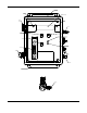
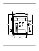
2.1 Exterior Features
The exterior of the instrument is shown in Figure 1. The exterior features are as follows:
Feature Description
Enclosure A NEMA-12 plastic box, approximately 10x8x6, with a clear hinged front cover.
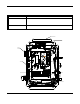
Sample Air Hose A six foot long hose to conduct a sample of the air from the source to the instrument.
See Figure 1A.
Sample Port The fitting for the sample air hose.
Sample/Calibration
Valve
A red handled ball valve which directs the air from either the sample or the calibrate port.
The handle points at the port, sample or calibrate, which is providing the air to the
instrument
Calibration Port The entrance for the calibration gas. The quick release fitting mates with one on the
calibration adapter.
Front Cover Latch
A quick-release latch that holds the clear front cover in place, and is capable of being
padlocked if desired.
Humidifier Tube Located under a black sheet metal cover. Is a tube that extracts moisture from the
atmosphere and adds it to dry sample air, before it is presented to the carbon monoxide and
oxygen sensors.
Line Cord A cord to supply 110 VAC to the equipment. Not illustrated.
Audio Alarm A loud horn activated by certain alarm conditions.
Mounting Flanges Flanges with holes for mounting the enclosure to a vertical surface.
Regulator To connect to the compressed air line. Regulator output to the ISA-200 RAL(O) should
be set to 55 PSI. See Figure 1A.
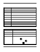
2.2 Display Panel Features
The display panel, shown in Figure 1, is viewed through the clear front cover of the enclosure, and is accessed by
opening the cover. Features are as follows:
Feature Description
Display A 2 line, 16 character per line, LCD with backlight. The numerical values of gas
concentrations, and other information are displayed.
Flowmeter A flow indicator located at the output of the sample flow stream, which indicates
quantitatively the flow of sample air or calibration gas through the instrument.
Visual Alarms On both sides of the display, a red LED for each sensor on the instrument.
Near the center of the panel,. a green power LED and a red fault LED,
Pushbutton Switches There are three of these, located near the center of the panel; they are yellow
rectangular membrane switches. They are:
Option Switch The top left switch.
Select Switch Directly to the right of the option switch.
Alarm Acknowledge/
Audio Defeat
Switch
Directly under the option switch.