
Owner's manual


ENMET Corporation ISA-44RAL-OD / ISA-44RAH-OD
10
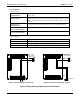
5. Apply 115 Vac and/or 12 Vdc power to the appropriate terminals (refer to Figure 2). As an emergency back-up
power source, both ac and dc power can be applied at the same time. Current will flow from the ac source. DC
current will flow only when the ac power is interrupted.
NOTE: 220 Vac power requires a change in the transformer hook-up. This change is best done at ENMET or an ENMET
service center.
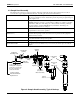
6. Attach the sample head of the ISA-44RAL-OD to the respiratory air line so that the sample air reaches the sensors
before the same respiratory air reaches the workers. If you have any problems involving the location of the unit,
contact your distributor or ENMET personnel. A technician will analyze the problem and provide recommendations
for a location.
CAUTION: Do not use a rubber hose to connect regulator to air line. This will cause inaccurate, upscale meter readings.
CAUTION: Do not locate the sample point on a low spot in the line. Water condensation may clog or damage the
regulator or sensor assembly. If you must locate the sample point at a low spot, install a water trap between
the air line and the sample head assembly.
NOTE: Because the ISA-44RAL-OD will be operating continuously, make sure that air is flowing over the sensors
continuously. Sensors exposed to stagnant or non-moving air may overheat or become contaminated.
NOTE: If pressure is applied to the regulator input, and air is not bubbling through the humidifier, the metering orifice
is probably plugged; you should replace it (Section 7.1).
7. Add tap water to the humidifier up to the Water Level mark.
8. Adjust the pressure regulator to align the gauge needle with the black dots marked"...SET" or between 7 – 12 PSI on
the dial.
9. Proceed to Section 5.0.
5.0 Initial Warm Up and Operation5.0 Initial Warm Up and Operation
5.1 Carbon Monoxide Detection Channel
Mount and install the ISA-44RAL-OD as outlined in Section 4.0.
NOTE: The unit has no ON/OFF switch. This safety monitoring device is designed to be powered and on at all times.
1. Rotate the operation switch to PURGE ON. This will silence the audio alarm, both alarm lights may go on soon; don't
worry, this is normal. They will turn off after awhile.
2. While operation switch is in PURGE ON position, measure purge voltage across TB2-6 and TB2-7. It should be 1.6
Vdc +/- .03 Vdc. If not 1.6 Vdc +/- .03 Vdc, adjust Purge Adjust Potentiometer (see Figure 2) until desired reading is
shown. Turn operation switch to HORN OFF position and measure sensor heater voltage across TB2-6 and TB2-7. It
should now read 0.86 Vdc +/- .03 Vdc. If not 0.86 Vdc +/- .03 Vdc, adjust Heater Adjust Potentiometer (see Figure
2) until desired reading is shown. Turn operation switch back to PURGE ON position.
3. Let clean air pass over the sensors for at least one hour. Clean Air Must Pass Over The Sensor. If you suspect
contaminated air or dirty conditions in your compressor, use bottled clean air. DO NOT operate the unit without air
passing over the sensor. If you do, you may contaminate or burn out the sensor.
4. The sensor is purged when the amber alarm light goes out, and the meter has stabilized.
5. Turn operation switch to HORN OFF position. Some meter drift is normal. The unit may show both green and red
lights momentarily at this point. This is also normal. After the sensor becomes stable, the red light will deactivate
and the green light will remain on, which is the normal operating state.
6. Turn the operation switch to OPERATE position.
Table 3: Reference, State of Operation of ISA-44RAL-OD / ISA-44RAH-OD
Normal operating state
• No alarms
• Green light on
Alarm state
• Green light off
• Amber light (low level alarm) or
• Amber light, Red light and Audio Alarm (high level alarm)
• Appropriate relay contacts in alarm position
Sensor fault or disconnected
• Green and red light on together.