USER MANUAL PTM 210 / PTM 215 / PTM 215U / PTM 215J DC Step code and later PTM 210 / PTM 215 PTM 215U PTM 215J Pushbutton transmitter modules DC Step code and later The product is protected by the following granted Patents: US7710227, DE10315765B4 US9614553, EP1312171B1, CN100508406C EP1389358B1, JP4225792B2 US7019241, EP1550202B1, DE50303733D1, CN1689218B US7391135, EP1611663B1, DE10315764B4, US8502470, JP5617103B2 EP2524572B1 And also by pending or not yet published Patents and Designs.
USER MANUAL PTM 210 / PTM 215 / PTM 215U / PTM 215J DC Step code and later REVISION HISTORY The following major modifications and improvements have been made from the first version of this document: No Major Changes 2.0 Update to modules with step code DC. 2.1 Update of certification numbers in US and Japan. Published by EnOcean GmbH, Kolpingring 18a, 82041 Oberhaching, Germany www.enocean.com, info@enocean.
USER MANUAL PTM 210 / PTM 215 / PTM 215U / PTM 215J DC Step code and later TABLE OF CONTENT 1 GENERAL DESCRIPTION .................................................................................... 5 1.1 Product variant and ordering codes .................................................................... 5 1.2 Basic Functionality ........................................................................................... 6 1.3 Typical Applications ..................................................
USER MANUAL PTM 210 / PTM 215 / PTM 215U / PTM 215J DC Step code and later 5 NFC INTERFACE CONFIGURATION – PTM 215 / PTM 215J / PTM 215U .................. 25 5.1 NFC interface overview ................................................................................... 25 5.2 NFC access protection ..................................................................................... 25 5.3 NFC parameters – Memory map ....................................................................... 25 5.3.
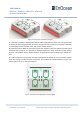
USER MANUAL PTM 210 / PTM 215 / PTM 215U / PTM 215J DC Step code and later 1 GENERAL DESCRIPTION The pushbutton transmitter family PTM 21x from EnOcean enables the implementation of wireless switches and remote controls without batteries. The PTM 21x pushbutton transmitters are self-powered (no batteries) and therefore maintenance-free. The power is provided by a built-in electro-dynamic power generator. The main application are wireless switches in smart buildings.
USER MANUAL PTM 210 / PTM 215 / PTM 215U / PTM 215J DC Step code and later 1.1.1 Previous / other product variants Previous versions of the PTM 21x product family (identified by step codes (DA and DB) contain only a subset of the functionality described in the document. Should you need information related to these products then please do not use this document as reference and refer to EnOcean support (support@enocean.com) for more details.
USER MANUAL PTM 210 / PTM 215 / PTM 215U / PTM 215J DC Step code and later Figure 3 Energy bow released & pressed It is therefore possible to distinguish between radio telegrams sent when the energy bow was pushed and radio telegrams sent when the energy bow was released. This makes it possible to distinguish between button press and button release actions.
USER MANUAL PTM 210 / PTM 215 / PTM 215U / PTM 215J DC Step code and later All PTM 21x devices support two operating modes - a normal mode and a secure mode with rolling code encryption to enable use in secure applications. Additionally, to the EnOcean Radio interface the PTM 215 modules include a NFC interface for device configuration. This NFC interface is powered by the NFC field of an NFC Reader or an NFC capable smartphone.
USER MANUAL PTM 210 / PTM 215 / PTM 215U / PTM 215J DC Step code and later Figure 6 Explosion drawing of complete wall switch with highlighted PTM Module © 2020 EnOcean | www.enocean.
USER MANUAL PTM 210 / PTM 215 / PTM 215U / PTM 215J DC Step code and later 1.4 Technical Data Power supply Electro-dynamic power generator Antenna PCB antenna Frequency PTM 210: 868.300 MHz (ASK)2 PTM 215: 868.300 MHz (ASK)1 PTM 215U: 902.875 MHz (FSK) PTM 215J: 928.
USER MANUAL PTM 210 / PTM 215 / PTM 215U / PTM 215J DC Step code and later 1.6 Environmental Conditions Operating temperature -25 °C up to +65 °C3 Storage temperature -25 °C up to +65 °C Humidity 0% to 95% r.h. Typical max. temperature difference between the PTM module (TX) and a receiver (RX) should not be bigger then 60 C°. 1.7 References [1] Mounting Instructions PTM https://www.enocean.com/products/enocean_modules/ptm-215/ [2] 2D and 3D model for PTM Rockers https://www.enocean.
USER MANUAL PTM 210 / PTM 215 / PTM 215U / PTM 215J DC Step code and later 2 2.1 FUNCTIONAL DESCRIPTION Block Diagram Figure 7 Block diagram of PTM 21x Energy Generator / Energy Bow Converts the motion of the energy bow into electrical energy. This is the main energy source for the operation of PTM Modules. Energy Converter Converts the energy of the energy generator into a stable DC supply voltage for the device electronics. Energy Management Secures energy supply of the module for the required period.
USER MANUAL PTM 210 / PTM 215 / PTM 215U / PTM 215J DC Step code and later NFC Interface The NFC interface represents the second communication interface of the PTM and it is designed for commissioning of the PTM device. Using the NFC module information, modes and runtime parameters can be read and in selected parameters also written. 2.2 Contact Nipples Assignment PTM 21x devices provide four contact nipples.
USER MANUAL PTM 210 / PTM 215 / PTM 215U / PTM 215J DC Step code and later in the radio telegram. Based on the EEP the receiver knows how to interpret telegrams received from a PTM module. In contrast to sensors which usually support one profile at a time, the encoding of PTM module does not vary between profiles (RPS profiles) and it up to the receiver to decide how the data should be interpreted. The receiver can describe what action (switch on / off the light, dim up / down, move shutters, …) to take.
USER MANUAL PTM 210 / PTM 215 / PTM 215U / PTM 215J DC Step code and later 3 OPERATING MODES This chapter describes the standard “out of the box” behaviour of PTM 21x devices. This standard behaviour e.g. mode selection or secure teach-in telegram transmission can be altered by the NFC Interface. Please refer to the chapter 5.4 for details.
USER MANUAL PTM 210 / PTM 215 / PTM 215U / PTM 215J DC Step code and later Figure 9 Example of harmful attacking scenarios PTM Modules are protected from For details on the secure mechanisms please refer to the security specification of the EnOcean Radio Protocol [3] together with the examples given in the application note4. Secure telegrams include a rolling code based on an incrementing counter (RLC) which guarantees that identical message content will be encrypted differently.
USER MANUAL PTM 210 / PTM 215 / PTM 215U / PTM 215J DC Step code and later The RLC counter is internally restarted to 0x0 once the AES key was changed via the NFC interface. After executing a factory reset (see chapter 3.4 for details), the PTM module returns to using the factory set security key but does not reset the RLC counter associated with the key. The last used RLC value associated with the factory security set key will be used. 3.2.
USER MANUAL PTM 210 / PTM 215 / PTM 215U / PTM 215J DC Step code and later Executing the special button combination for secure mode 2x nipple SBC or 3x nipple SBC – see chapter 3.3 for details. Trigger through the NFC interface. Key Secure Teach-in Parameters are specified as following: Type of the Teach-in_info in the secure teach-in telegram (Teach_In_Info : Type) is: 1-PTM. Info of the Teach-in_info in the secure teach-in telegram (Teach_In_Info : Info) is: 0-Rocker A / 1-Rocker B.
USER MANUAL PTM 210 / PTM 215 / PTM 215U / PTM 215J DC Step code and later Figure 10 2 nipple SBC - channel A left, channel B right 3 nipple SBC – pressing any 3 nipples, which results in 4 different combinations. This SBC is used to enter the secure mode with explicit RLC. The picture below shows the possible options for this SBC. Figure 11 3 nipple SBC - 4 different options 4 nipple SBC – pressing all 4 nipples. This SBC is used to enter the normal mode and execute factory reset.
USER MANUAL PTM 210 / PTM 215 / PTM 215U / PTM 215J DC Step code and later 2 SBC 3 SBC 4 SBC Energy bow press N/A N/A Switch to Normal Mode Energy bow press/release Transmit secure teach in – Transmit secure teach in – if current mode is security if current mode is security N/A with implicit RLC. with explicit RLC. Energy bow press/release/press Switch to Security mode Switch to Security mode with implicit RLC & trans- with explicit RLC & trans- N/A mit secure teach-in. mit secure teach-in.
USER MANUAL PTM 210 / PTM 215 / PTM 215U / PTM 215J DC Step code and later 4 Radio Communication The PTM module transmits radio telegrams based on the EnOcean Alliance Radio standard. The Radio standard uses the ISO/IEC standard on the lowest protocol level. There are two version of the EnOcean Radio Protocol: 1. “EnOcean Radio Protocol 1” – ERP 1 based on ISO/IEC 14543-3-10 mostly present in Europe & China 2.
USER MANUAL PTM 210 / PTM 215 / PTM 215U / PTM 215J DC Step code and later Figure 13 Normal mode ULP substitution to RPS RORG The ULP has a value of 0x5 or 0x6 defined by the switch action. It is described in the EEP, see chapter 2.3 for details on the EEP. It is then substituted to 0xF6 (RPS). DATA Is defined as payload of the EEP, see chapter 2.3 for details on EEP. No change during extension. TXID Represents the EnOcean Unique ID. No change during extension.
USER MANUAL PTM 210 / PTM 215 / PTM 215U / PTM 215J DC Step code and later Figure 14 Secure mode ULP substitution to encrypted RPS RORG The secure low power switch RORG field code 0x7F is substituted by the secure telegram RORG (0x30) defined in the EnOcean Security Specification [3]. DATA Is defined as payload of the EEP, see chapter 2.3 for details on EEP. No change in field when extended. MAC Message Authentication Cypher – defined in the EnOcean Security Specification.
USER MANUAL PTM 210 / PTM 215 / PTM 215U / PTM 215J DC Step code and later For details on encrypted RPS telegrams please see the EnOcean Security specification [3]. 4.2 ERP 2 Communication The ERP2 frames are fully described by the ERP2 specification. In the ERP2, there are no ULP frames defined and the PTM module uses the common definition. The ERP2 frame is defined as follows: The relevant fields are defined below, for other fields and details please consult the ERP2 specification.
USER MANUAL PTM 210 / PTM 215 / PTM 215U / PTM 215J DC Step code and later 5 NFC INTERFACE CONFIGURATION – PTM 215 / PTM 215J / PTM 215U 5.1 NFC Interface Overview PTM 215 implements an NFC configuration interface that can be used to access (read and write) the PTM 215 configuration memory and thereby configure the device as described in the following chapters. NFC communication distance is for security reasons set to require direct contact between the NFC reader and the PTM 215 device.
USER MANUAL PTM 210 / PTM 215 / PTM 215U / PTM 215J DC Step code and later User Information NDEF string (Public read / write access; no PIN required) This area allows any user to read or write information about the device such as the intended installation location or additional instructions. 2. Binary data area NFC HEADER (Public read-only access; no PIN required) This area contains information about the NFC revision.
USER MANUAL PTM 210 / PTM 215 / PTM 215U / PTM 215J DC Step code and later 5.3.1 Device Identification NDEF The NDEF area contains a device identification string using the NDEF (NFC Data Exchange Format) standard that is readable by most NFC-capable reader devices (including smartphones). The NDEF content can be read also by conventional NTAG commands, but this is then executed in “binary” mode. The conversion to a string is achieved by applying UTF-8 decoding.
USER MANUAL PTM 210 / PTM 215 / PTM 215U / PTM 215J DC Step code and later The structure of the NFC HEADER area is described in detail in the EnOcean Alliance specification - NFC Memory Structure for Eco-system products, for details see reference [3]. Details are also shown in the table below.
USER MANUAL PTM 210 / PTM 215 / PTM 215U / PTM 215J DC Step code and later The END field identifies the end of the NFC header and is always set to 0xFE. The number of bytes from START to END must equal LENGTH, otherwise the NFC header is invalid. 5.3.4 Configuration The CONFIGURATION area allows the configuration of the device parameters. Configuration registers larger than 8 bit use big endian format, i.e. the most significant byte comes first.
USER MANUAL PTM 210 / PTM 215 / PTM 215U / PTM 215J DC Step code and later 5.3.4.2 NEW NFC PIN The NFC PIN used to protect access to the CONFIGURATION memory area should be changed from the default value to a user-specific value to avoid unauthorized access to the NFC device configuration interface. To do so, first authenticate with the current NFC PIN and then write the new NFC PIN (32-bit value) to memory. The new NFC PIN will be applied to the PTM module after pressing & releasing the energy bow.
USER MANUAL PTM 210 / PTM 215 / PTM 215U / PTM 215J DC Step code and later 5.3.4.5 NEXT OEPRATION IS TEACH IN The module will send a Security Teach-in telegram the next time it is triggered. The module must first be set to the desired security level. After the secure Teach in telegram was send this flag is reset to default state. Following values can be set 0b00000000: 0b00000001: OFF (default): Normal operation. ON: Next telegram will be a Security Teach-in telegram.
USER MANUAL PTM 210 / PTM 215 / PTM 215U / PTM 215J DC Step code and later Once the key was written the PTM 215 will automatically use the new written key and reset the RLC sequence to 0x0. To return to the factory defined key a factory reset as described in chapter 3.4 must be executed. Note that the USER_KEY register is a write-only register meaning that it is not possible to read back a user-defined security key. © 2020 EnOcean | www.enocean.
USER MANUAL PTM 210 / PTM 215 / PTM 215U / PTM 215J DC Step code and later 5.4 NFC Interaction with the PTM Application The PTM 215 application is not powered by the NFC interface during NFC communication. After parameters in the NFC memory were changed, the energy bow has to be pressed and released so that the PTM application can read the new parameters, verify and apply them. For this purpose, also a special FLAG register must be set to notify the PTM Application about configuration changes.
USER MANUAL PTM 210 / PTM 215 / PTM 215U / PTM 215J DC Step code and later and NFC readers such as NFC-enabled smartphones or tablets. It can be used to determine all essential product parameters. The app is mainly aimed at OEMs and installers. They can also use the application to integrate NFC devices into existing systems.
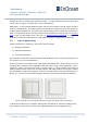
USER MANUAL PTM 210 / PTM 215 / PTM 215U / PTM 215J DC Step code and later 5.5.2 EnOcean NFC Configurator Figure 20 EnOcean NFC Configurator EnOcean provides the NFC Configurator for all OEM Partners to configure and commission EnOcean GmbH products with NFC interface. NFC Configurator is a PC application enabling to write / read all accessible parameters specified for the product. Configured parameters can also be stored into a separate file, reopened and shared with other users.
USER MANUAL PTM 210 / PTM 215 / PTM 215U / PTM 215J DC Step code and later OEMs wanting to develop own NFC configuration tools or to include NFC configuration into their existing tools can accelerate their development by licensing the EnOcean SW libraries and the EnOcean reference implementation. Please contact EnOcean: support@enocean.com for more information or a commercial offer. © 2020 EnOcean | www.enocean.
USER MANUAL PTM 210 / PTM 215 / PTM 215U / PTM 215J DC Step code and later 6 6.1 APPLICATIONS INFORMATION Product Label Listed below are the product labels for each of the PTM 21x modules. Each module can easily be identified by its name and the supported frequency (868.300 MHz 902.875 MHz, 928.350 MHz) on the label. Additionally, PTM 215 devices (which contain the NFC interface for configuration) can be identified by the NFC icon on the product label.
USER MANUAL PTM 210 / PTM 215 / PTM 215U / PTM 215J DC Step code and later Field Meaning Examples Product name PTM 210 / PTM 215 / PTM 215J / PTM 215U EnOcean Order code S3001-A210 / S3001-A215 / S3051-A215 / S3061-A215 Step code Product version DC / DD / DE etc. Production date Week of year / production 40 / 18 (40th week in 2018) Year Model Order code NFC capability information – showing the position of the antenna. Frequencies: 868.3 MHz, Certification marking of the 902.875 MHz, 928.
USER MANUAL PTM 210 / PTM 215 / PTM 215U / PTM 215J DC Step code and later 6.2 Content of QR codes Reading the QR code will return a text string formatted according the EnOcean Alliance Labelling standard. Details about the labelling standard can be found here: https://www.enocean-alliance.org/productid/. The same standard is also used to specify the NDEF String content.
USER MANUAL PTM 210 / PTM 215 / PTM 215U / PTM 215J DC Step code and later Identifier 30S Value Length of data 000001500100 15 characters (12 data) Static Source Address (hex), EnOcean Radio ID 48 bit format + 13Z Field Separator 1 character 12345678123456781234567812345678 35 characters (32 data) Security AES key (16 Bytes), generated and specific for each device + Field Separator 1 character 1P 000B00000057 14 characters (12 data) Product ID (EnOcean Alliance), + 30P Field Separator 1 c
USER MANUAL PTM 210 / PTM 215 / PTM 215U / PTM 215J DC Step code and later It is recommended using non-conductive material for the rockers to ensure best transmission range. Avoid if possible metallic materials or plastics with conducting ingredients such as graphite. If the rocker is not mounted on the rotation axis of PTM 21x several tolerances have to be considered! The measure from support plane to top of the energy bow is 7.70 mm +/- 0.
USER MANUAL PTM 210 / PTM 215 / PTM 215U / PTM 215J DC Step code and later 6.5 Transmission Range The main factors that influence the system transmission range are: Type and location of the antennas of receiver and transmitter. Type of terrain and degree of obstruction of the link path. Sources of interference affecting the receiver. “Dead spots” caused by signal reflections from nearby conductive objects.
USER MANUAL PTM 210 / PTM 215 / PTM 215U / PTM 215J DC Step code and later 7 AGENCY APPROVALS 7.1 PTM 210 and PTM 215: Radio Approval for the European Market The module is developed and tested according to the R&TTE EU-directive on radio equipment. The assembly conforms to the European and national requirements of electromagnetic compatibility. The conformity has been proven and the corresponding documentation has been deposited at EnOcean.
USER MANUAL PTM 210 / PTM 215 / PTM 215U / PTM 215J DC Step code and later 7.3 PTM 215U: FCC and Industry Canada Regulatory Statements This device complies with part 15 of the FCC rules and Industry Canada ICES- 003. Operation is subject to the following two conditions: (1) This device may not cause harmful interference, and (2) this device must accept any interference received, including interference that may cause undesired operation.
USER MANUAL PTM 210 / PTM 215 / PTM 215U / PTM 215J DC Step code and later 7.4 PTM 215J: Japanese Type Approval PTM 215J complies with the Japanese radio law and is certified according to ARIB STD-T108 V1.0 (2012-02). There is a certification marking on the back side of the module. When the product is placed on the Japanese market, it must carry the Specified Radio Equipment marking as shown below: 206-000603 If the certification label cannot be recognized from outside (e.g.