
User's Manual


© 2020 EnOcean | www.enocean.com PTM 210 / PTM 215 / PTM 215U / PTM 215J User Manual August 2020 | Page 12/45
USER MANUAL
PTM 210 / PTM 215 / PTM 215U / PTM 215J
DC Step code and later
2 FUNCTIONAL DESCRIPTION
2.1 Block Diagram
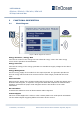
Figure 7 Block diagram of PTM 21x
Energy Generator / Energy Bow
Converts the motion of the energy bow into electrical energy. This is the main energy
source for the operation of PTM Modules.
Energy Converter
Converts the energy of the energy generator into a stable DC supply voltage for the device
electronics.
Energy Management
Secures energy supply of the module for the required period. The generator provides an
burst of energy which needs to be conserved for the much longer period than the burst
lasts.
Microcontroller
Determines the status of the contact nipples and the energy bow, encodes this status into a
EnOcean Data telegram, if required it encrypts this data and computes the authentication
signature, generates the proper radio telegram structure and sends it to the radio
transmitter.
RF Transmitter
Transmits the data as a series of short EnOcean radio telegrams.
Contact Nipples
Via the 4 contact nipples the rockers or other custom plastics can code specific information
into the radio telegram triggering different functions at the receiver.