
User's Manual


© 2020 EnOcean | www.enocean.com PTM 210 / PTM 215 / PTM 215U / PTM 215J User Manual August 2020 | Page 13/45
USER MANUAL
PTM 210 / PTM 215 / PTM 215U / PTM 215J
DC Step code and later
NFC Interface
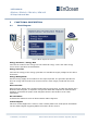
The NFC interface represents the second communication interface of the PTM and it is de-
signed for commissioning of the PTM device. Using the NFC module information, modes and
runtime parameters can be read and in selected parameters also written.
2.2 Contact Nipples Assignment
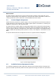
PTM 21x devices provide four contact nipples. They are grouped into two channels (Channel
A and Channel B) each containing two contact nipples (State O and State I). Resulting the
nipples are referred to as: AO, AI, BO and BI.
The state of all four contact nipples is transmitted together with a unique device identification
whenever the energy bow is pushed or released as a part of an EnOcean radio telegram. The
exact encoding is defined in the EEP Profile. Which EEP is used is based on the Radio Standard
(ERP1 or ERP2) and operating mode (normal or secure). See chapter 2.3 for details on used
EEPs.
The picture below shows the arrangement of the four nipples and their designation:
Figure 8 Contact nipple designation
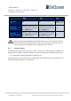
2.3 Available EnOcean Equipment Profiles
The (EnOcean Equipment Profile) EEP profile defines how the data inside the EnOcean tele-
gram is encoded. It practically means how the nipples and energy bow state are represented