
User's Manual


© 2020 EnOcean | www.enocean.com PTM 210 / PTM 215 / PTM 215U / PTM 215J User Manual August 2020 | Page 28/45
USER MANUAL
PTM 210 / PTM 215 / PTM 215U / PTM 215J
DC Step code and later
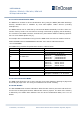
The structure of the NFC HEADER area is described in detail in the EnOcean Alliance specifi-
cation - NFC Memory Structure for Eco-system products, for details see reference [3]. Details
are also shown in the table below.
NFC Address
Content
Byte 0
Byte 1
Byte 2
Byte 3
0x31
START (0xE0)
LENGTH (0x0A)
VERSION (0x01)
MAN ID MSB (0x00)
0x32
MAN ID LSB(0x0B)
NFC Struct ID (0x000001)
0x33
REVISION (0x02)
END (0xFE)
UNUSED (0x0000)
Figure 15 – NFC HEADER area structure
The NFC HEADER contains the following fields:
START
This field identifies the start of the NFC header and is always set to 0xE0.
LENGTH
This field identifies the length of the NFC header.
This field is set to 0x0A since the header structure is 10 bytes long.
VERSION
This field identifies the major revision of the NFC specification.
MAN ID
The 16-bit Manufacturer ID is assigned by the EnOcean Alliance.
The field identifies the manufacturer of the device so that manufacturer-specific layout
implementations can be determined.
For EnOcean GmbH products this field is set to 0x000B.
NFC Struct ID
The 24-bit NFC Struct ID field identifies an individual device from the range of devices
manufactured by the manufacturer specified in the Manufacturer ID field.
For PTM 215, the NFC Struct ID is set to 0x000001.
REVISION
The REVISION field identifies the exact revision of the NFC layout.
The REVISION will be incremented whenever a change to the NFC layout is made.
Changes are possible only when 100% backwards compatible to all previous revisions.
If changes are not compatible a new NFC Struct ID must be defined.
END