
User's Manual


© 2020 EnOcean | www.enocean.com PTM 210 / PTM 215 / PTM 215U / PTM 215J User Manual August 2020 | Page 29/45
USER MANUAL
PTM 210 / PTM 215 / PTM 215U / PTM 215J
DC Step code and later
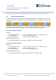
The END field identifies the end of the NFC header and is always set to 0xFE. The
number of bytes from START to END must equal LENGTH, otherwise the NFC header
is invalid.
5.3.4 Configuration
The CONFIGURATION area allows the configuration of the device parameters. Configuration
registers larger than 8 bit use big endian format, i.e. the most significant byte comes first.
Read or write access to the CONFIGURATION area is only possible after unlocking the memory
using the correct 32-bit PIN code. See chapter 5.2 for details.
Before making any changes to the default configuration, be sure to familiarize yourself with
the functionality of the device and the effect of the intended changes.
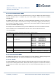
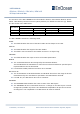
The structure of the CONFIGURATION area is defined by the NFC Struct ID as described in
chapter 5.3.3 and is shown in Figure 16 below.
NFC
Address
Content
Byte 0
Byte 1
Byte 2
Byte 3
0x40
FLAG
RFU
0x41
NEW NFC PIN
0x42
SECURITY LEVEL
ALLOW TEACH IN
NEXT OPERATION
IS TEACH IN
RFU
0x43
RFU
0x44
…
0x47
USER KEY (128 Bit)
(Write Only - Will be reset to zero after it has been copied to internal memory)
Can be used as alternative security key instead of FACTORY_KEY
0x48
PRODUCT ID
(String with 12 characters “e.g. 000B00000053” in UTF-8 format – to be copied to NDEF)
0x49
0x4A
Figure 16 – CONFIGURATION area structure
Each field is explained in the following chapters.
5.3.4.1 FLAG
This field needs to be changed to 0x55 to make the PTM application aware of the executed
changes. Without setting this field to 0x55 the changes will not be considered by the PTM
application.