
User's Manual

USER MANUAL PREVIEW
PTM 535BZ – BLUETOOTH AND ZIGBEE GREEN POWER PUSHBUTTON TRANSMITTER
© 2022 EnOcean | www.enocean.com F-710-017, V1.0 PTM 535BZ User Manual | v1.2 | July 2021 | Page 50/121
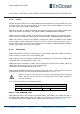
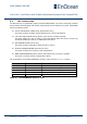
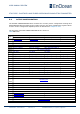
Table 13 – ACTIVE CONFIGURATION structure
5.6.1 INPUT_CONFIG
The ECO_DIRECTION field of the INPUT_CONFIG register is used to define which direction
of the ECO 200 harvester is considered as a press event and which as a release event.
The default configuration is that a movement of the ECO 200 harvester spring away from
the PTM 535BZ PCB is considered as a press event while a movement of the ECO 200 har-
vester spring towards the PTM 535BZ PCB is considered as a release event as described in
chapter 2.4.1.
If ECO_DIRECTION status bit is set, then this logic is inverted meaning that a movement of
the ECO 200 harvester spring away from the PTM 535BZ PCB is considered as release event
while a movement of the ECO 200 harvester spring towards the PTM 535BZ PCB is consid-
ered as press event.
Additionally, the input signals INPUT1 and INPUT2 described in chapter 2.4.2 can be disa-
bled using the corresponding status bits INPUT1 and INPUT2. If an input is disabled, then it
will always be treated as if it is not connected.
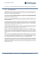
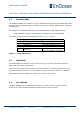
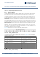
Figure 36 below shows the structure of the INPUT_CONFIG register.
Figure 36 – INPUT_CONFIG register
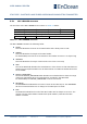
The bit fields within the INPUT_CONFIG register are shown in Table 14 below. The default
settings are shown in bold.
Bit Configuration Option Supported Settings
0
ECO_DIRECTION
Selects the ECO 200 direction considered as “Press”
0b0: Standard (Press = Away from PCB)
0b1: Inverted (Press = Towards PCB)
1
INPUT1
Enables / disables INPUT1
0b0: Enabled
0b1: Disabled (INPUT1 is considered disconnected)
2
INPUT1
Enables / disables INPUT2
0b0: Enabled
0b1: Disabled (INPUT2 is considered disconnected)
3 RFU 0b0 (Always set to 0b0)
4 RFU 0b0 (Always set to 0b0)
5 RFU 0b0 (Always set to 0b0)
6 RFU 0b0 (Always set to 0b0)
7 RFU 0b0 (Always set to 0b0)
Table 14 – INPUT_CONFIG settings