
User's Manual


USER MANUA
L
V0.82
© 2010 EnOcean | www.enocean.com TCM 300 / 300C / 320 / 320C User Manual V0.82 | Page 9/43
TCM 300 / 300C / 320 / 320C
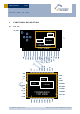
2 .2 Pin description a nd operat iona l characterist ics
Symbol Function Characteristics
GND Ground connection Must be connected to GND
VDD Supply voltage TCM 300/300C: 2.5 V – 4.5 V
TCM 320/320C: 2.5 V – 3.3 V
Max. ripple: see 2.4
RVDD
RF supply voltage
regulator output
1.8 V
Output current:
max. 100 µA with built-in firmware (RX on)
max. 10 mA while not in RX/TX mode
DVDD
Digital supply voltage
regulator output
1.8 V
Output current: max. 5 mA
IOVDD
Digital interface supply
voltage
TCM 320/320C: internally connected to VDD
TCM 300/300C: Must be connected to desired
interface supply between 1.8 V and 3.3 V
See also 2.2.1.
RESET Reset input
Programming I/F
Active high reset (1.8 V). External 1 kΩ pull-
down required.
PROG_EN
Programming I/F HIGH: programming mode active
LOW: operating mode
Digital input, external 1 kΩ pull-down required.
ADIO0
MODE_SEL Analog input: At start-up input voltage is
measured and mode is selected. See chapter
2.6
MODE 0: not used
In mode 0 the repeater level is 1 and
cannot be modified.
ADIO1
MODE 1-4: REP_LEVEL Mode 1-4: At start-up the repeater level
is selected:
Repeater level 1: LOW
Repeater level 2: HIGH
Digital input, internal pull-up active
ADIO2 REPEATER At start-up the repeater can be switched on:
Repeater on: LOW
Repeater off: HIGH
Digital input, internal pull-up active
MODE 0: Sensitivity Low sensitivity: LOW
High sensitivity: HIGH
Digital input, internal pull-up active
ADIO3
MODE 1-4: LRN
Enter/leave teach-in mode. See chapter 2.8
Digital input, internal pull-up active
MODE 0: not used Internal pull-up active ADIO4
MODE 1-4: CLR
Clear ID memory. See chapter 2.8
Digital input, internal pull-up active
ADIO5 Not used Digital output, internally set to LOW
MODE 0-1: SER_RX UART input ADIO6
MODE 2-4: not used Digital input, internal pull-up active