USER MANUAL V0.6 Scavenger Transmitter Module STM 31x / STM 31xC September 7, 2010 Observe precautions! Electrostatic sensitive devices! Patent protected: WO98/36395, DE 100 25 561, DE 101 50 128, WO 2004/051591, DE 103 01 678 A1, DE 10309334, WO 04/109236, WO 05/096482, WO 02/095707, US 6,747,573, US 7,019,241 EnOcean GmbH Kolpingring 18a 82041 Oberhaching Germany Phone +49.89.67 34 689-0 Fax +49.89.67 34 689-50 info@enocean.com www.enocean.
USER MANUAL V0.6 STM 31X / STM 31XC REVISION HISTORY The following major modifications and improvements have been made to the first version of this document: No 0.5 0.6 Major Changes Initial version New drawings added, Agency approvals added Published by EnOcean GmbH, Kolpingring 18a, 82041 Oberhaching, Germany www.enocean.com, info@enocean.
USER MANUAL V0.6 STM 31X / STM 31XC TABLE OF CONTENT 1 2 3 4 GENERAL DESCRIPTION................................................................................. 4 1.1 Basic functionality ......................................................................................... 4 1.2 Technical data .............................................................................................. 5 1.3 Physical dimensions......................................................................................
USER MANUAL V0.6 STM 31X / STM 31XC 1 GENERAL DESCRIPTION 1.1 Basic functionality The extremely power saving RF transmitter module STM 31x of EnOcean enables the realization of a wide range of wireless and maintenance free sensors such as temperature sensors, humidity sensors, or room operating panels. Power supply is provided by a small solar cell, an external energy harvester, or an external 3V battery. An energy storage is installed to bridge periods with no supply from the energy harvester.
USER MANUAL V0.6 STM 31X / STM 31XC 1.2 Technical data Antenna Frequency Radio Standard Data rate/Modulation type Conducted Output Power Power Supply @ VDD Initial operation time in darkness @ 25°C Operation start up time with empty energy store Input Channels Radio Regulations 1.3 whip or helical antenna installed 315.0 MHz (STM 31xC)/868.3 MHz (STM 31x) EnOcean 868 MHz/315 MHz 125 kbps/ASK typ. 2 dBm Pre-installed solar cell (except STM312 / STM312C) Illumination 50-100000 lux 2.1 V–5.0 V, 2.
USER MANUAL V0.6 STM 31X / STM 31XC © 2010 EnOcean | www.enocean.com STM 31x / STM 31xC User Manual V0.
USER MANUAL V0.6 STM 31X / STM 31XC 1.4 Environmental conditions Operating temperature -20 °C … +60 °C Storage temperature Humidity 1.5 -20 °C … +60 °C 0% … 93% r.h., non-condensing Ordering Information Type STM 310 STM 311 STM 312 STM 310C STM 311C STM 312C Ordering Code S3001-D310 S3001-D311 S3001-D312 S3031-D310 S3031-D311 S3031-D312 © 2010 EnOcean | www.enocean.com Frequency 868.3 MHz 868.3 MHz 868.3 MHz 315.0 MHz 315.0 MHz 315.0 MHz STM 31x / STM 31xC User Manual V0.
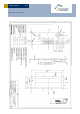
USER MANUAL V0.6 STM 31X / STM 31XC 2 FUNCTIONAL DESCRIPTION 2.1 Simplified firmware flow chart and block diagram © 2010 EnOcean | www.enocean.com STM 31x / STM 31xC User Manual V0.
USER MANUAL V0.6 STM 31X / STM 31XC Whip or helical antenna VCHAR VDD BALUN 16MHz Oscillator DOLPHIN EO3000I UVDDext WAKE0 LRN Power management RF Transmitter Transmit Indicator 868.3 MHz (STM31x) 315.0 MHz (STM31xC) LED Micro Controller Spontaneous wake-up DI_0 DI_1 DI_2 LRN button CW_1 CW_0 Cyclic Wake-up (every 100th, every 10th, every cyclic wake-up or SW defined) RESET AD_0 AD_1 AD_2 A/D Energy Storage Solar Cell VGC 2.
USER MANUAL V0.6 STM 31X / STM 31XC 2.3 Pin description and operational characteristics STM 31x H ardw are Sym bol GND VDD STM 31x Firm w are Sym bol GND VDD VCHAR VCHAR VGC VGC SWPWR SWPWR (= switched DVDD) Function C haracteristics Ground connection Supply voltage 2.1 V – 5.0 V; Start-up voltage: 2.6 V Maximum ripple: see 2.6 Connection of external 3 V battery possible Charging input Input for external energy harvester (for use in STM 312). See 2.10.
USER MANUAL V0.6 STM 31X / STM 31XC ADIO6 DI_2 Digital input ADIO7 LED SCSEDIO0 CW_1 Transmission indicator LED Programming I/F Encoding input for wake-up cycle SCLKDIO1 CW_0 Programming I/F Encoding input for wake-up cycle WSDADIO2 CP_1 Programming I/F Encoding input for retransmission RSDADIO3 CP_0 Programming I/F Encoding input for retransmission WAKE0 WAKE0 Programming I/F Wake input WAKE1 LRN LRN input Input read ~2 ms after wake-up. See 2.7.2.
USER MANUAL V0.6 STM 31X / STM 31XC 2.3.2 Analog and digital inputs Parameter Analog Input Measurement range Conditions / Notes Min Single ended Typ 0.05 Input coupling Measurement bandwidth Input resistance RVDD0.05 DC 100 Single ended against RGND @ 1 kHz Input capacitance Single ended against RGND @ 1 kHz Effective measurement resolution Configurable, see 2.7.2 Related to the reference Relative measurement accuracy voltage within specified input range Digital Input Mode 10 6 2.4 pF 10 0.
USER MANUAL V0.6 STM 31X / STM 31XC 2.6 Power management and voltage regulators Symbol Parameter Conditions / Notes Voltage Regulators Ripple on VDD, where VDDR Min(VDD) > VON UVDD Ultra Low Power supply RVDD RF supply Internal signal only DVDD Digital supply Internal signal only Threshold Detector VON Turn on threshold Automatic shutdown if VOFF Turn off threshold VDD drops below VOFF Min Typ Max Units 50 mVpp 1.7 1.7 1.8 1.8 1.8 1.9 1.9 V V V 2.3 1.85 2.45 1.9 2.6 2.
USER MANUAL V0.6 STM 31X / STM 31XC Redundant retransmission Via CP_0 and CP_1 an internal counter is set which is decreased at every wake-up signal. Once the counter reaches zero the redundant retransmission signal is sent.
USER MANUAL V0.6 STM 31X / STM 31XC 2.7.2 Configuration via serial interface Via the programming interface the configuration area can be modified. This provides a lot more configuration options. Values set via serial interface override hardware settings! These settings are read after RESET or power-on reset only and not at every wake-up of the module! Parameter Configuration via pins See section 2.7.
USER MANUAL V0.6 STM 31X / STM 31XC EnOcean provides EOPx (EnOcean Programmer, a command line program) and Dolphin Studio (Windows application for chip configuration, programming, and testing) and the USB/SPI programmer device as part of the EDK 300 developer´s kit. 2.8 Radio telegram 2.8.1 Normal operation Telegram content (seen at serial interface of RCM 130/TCM 3x0 or at DOLPHIN API): ORG = 0x07 (Telegram type “4BS”) Data_Byte1..
USER MANUAL V0.6 STM 31X / STM 31XC 2.8.2 Teach-in telegram In case of a wake-up via WAKE1 pin (LRN input) the module transmits a teach-in telegram. If the manufacturer code is not set, the module transmits a normal telegram according to 2.8.1 with the difference that DI_3=0. If a manufacturer code is set, this teach-in telegram contains special information as described below.
USER MANUAL V0.6 STM 31X / STM 31XC 2.10 Charging circuitry The figure below shows the internal charging circuit. It is controlled via the WXODIO pin of EO3000I which switches according to the status of the internal threshold detector. For details please refer to our Dolphin Core Description documentation. An external 3 V battery can be connected at VDD (STM 312 only) or at VGC. 2.11 Energy consumption 100 10 Current[m A ] 1 0.1 0.01 0.001 0.0001 0.
USER MANUAL V0.6 STM 31X / STM 31XC From these values the following performance parameters have been calculated: Wake cycle [s] 1 1 1 10 10 10 100 100 100 Operation Time in darkness [h] Transmit when storage interval fully charged 1 10 100 1 10 100 1 10 100 0.5 1.7 2.1 5.
USER MANUAL V0.6 STM 31X / STM 31XC 3 APPLICATIONS INFORMATION 3.1 Using the WAKE pins The logic input circuits of the WAKE0 and WAKE1 pins are supplied by UVDD and therefore also usable in “Deep Sleep Mode”. Due to current minimization there is no internal pull-up or pull-down at the WAKE pins. When STM 31x is in “Deep Sleep Mode” and the logic levels of WAKE0 and / or WAKE1 is changed, STM 31x starts up.
USER MANUAL V0.6 STM 31X / STM 31XC If more digital inputs with WAKE functionality are needed in an application, WAKE0 can be combined with some of the digital inputs as shown below: © 2010 EnOcean | www.enocean.com STM 31x / STM 31xC User Manual V0.
USER MANUAL V0.6 STM 31X / STM 31XC 3.2 Antenna options 3.2.1 Whip antenna (STM 310, STM 310C, STM 312, STM 312C) Specification of the whip antenna; L=150 mm @ 315 MHz, L=86 mm @ 868 MHz Antenna layout recommendation: STM 31x without host PCB STM 31x with host PCB 868MHz: > 1cm 315MHz: > 2cm 868MHz: > 2cm 315MHz: > 4cm Glass, wood, concrete, metal Host PCB GND plane 868MHz: > 2cm 315MHz: > 4cm © 2010 EnOcean | www.enocean.com STM 31x / STM 31xC User Manual V0.
USER MANUAL V0.6 STM 31X / STM 31XC 3.2.2 Helical antenna (STM 311, STM 311C) 868 MHz 315 MHz Antenna recommendation: STM 31x without host PCB STM 31x with host PCB 868MHz: > 5mm 315MHz: > 10mm Plastic 868MHz: > 2mm 315MHz: > 4mm © 2010 EnOcean | www.enocean.com Host PCB GND plane Glass, wood, concrete, metal STM 31x / STM 31xC User Manual V0.
USER MANUAL V0.6 STM 31X / STM 31XC 3.3 Transmission range The main factors that influence the system transmission range are type and location of the antennas of the receiver and the transmitter, type of terrain and degree of obstruction of the link path, sources of interference affecting the receiver, and “Dead” spots caused by signal reflections from nearby conductive objects.
USER MANUAL V0.6 STM 31X / STM 31XC 4 AGENCY CERTIFICATIONS The modules have been tested to fulfil the approval requirements for CE (STM 31x) and FCC/IC (STM 31xC) based on the built-in firmware. When developing customer specific firmware based on the API for this module, special care must be taken not to exceed the specified regulatory limits, e.g. the duty cycle limitations! 4.
USER MANUAL V0.6 STM 31X / STM 31XC 4.2 FCC (United States) certification STM 31xC LIMITED MODULAR APPROVAL This is an RF module approved for Limited Modular use operating as an intentional transmitting device with respect to 47 CFR 15.231(a-c) and is limited to OEM installation. The module is optimized to operate using small amounts of harvested energy, such as can be collected by a small solar cell exposed to ambient light.
USER MANUAL V0.6 STM 31X / STM 31XC OEM Requirements In order to use EnOcean’s FCC ID number, the OEM must ensure that the following conditions are met. End users of products, which contain the module, must not have the ability to alter the firmware that governs the operation of the module. The agency grant is valid only when the module is incorporated into a final product by OEM integrators. The end-user must not be provided with instructions to remove, adjust or install the module.
USER MANUAL V0.6 STM 31X / STM 31XC Model STM 310C STM 312C STM 311C 4.3 Type Pre-installed Wire/Monopole Gain 1.0 dBi Pre-installed helical antenna -9 dBi IC (Industry Canada) certification In order to use EnOcean’s IC number, the OEM must ensure that the following conditions are met: Labeling requirements for Industry Canada are similar to those required by the FCC. The Original Equipment Manufacturer (OEM) must ensure that IC labeling requirements are met.
USER MANUAL V0.6 Scavenger Transmitter Module STM 320 / STM 320C / STM 321C September 10, 2010 Observe precautions! Electrostatic sensitive devices! Patent protected: WO98/36395, DE 100 25 561, DE 101 50 128, WO 2004/051591, DE 103 01 678 A1, DE 10309334, WO 04/109236, WO 05/096482, WO 02/095707, US 6,747,573, US 7,019,241 EnOcean GmbH Kolpingring 18a 82041 Oberhaching Germany Phone +49.89.67 34 689-0 Fax +49.89.67 34 689-50 info@enocean.com www.enocean.
USER MANUAL V0.6 STM 320 / STM 320C / STM 321C REVISION HISTORY The following major modifications and improvements have been made to the first version of this document: No 0.5 0.6 Major Changes Initial version New drawings added; new energy consumption data added; application note for connecting an external battery added; Agency certifications added Published by EnOcean GmbH, Kolpingring 18a, 82041 Oberhaching, Germany www.enocean.com, info@enocean.
USER MANUAL V0.6 STM 320 / STM 320C / STM 321C TABLE OF CONTENT 1 1.1 1.2 1.3 1.4 1.5 2 2.1 2.2 2.3 2.4 3 3.1 3.2 3.3 4 4.1 4.2 4.3 GENERAL DESCRIPTION................................................................................. 4 Basic functionality ......................................................................................... 4 Technical data .............................................................................................. 4 Physical dimensions..............................
USER MANUAL V0.6 STM 320 / STM 320C / STM 321C 1 GENERAL DESCRIPTION 1.1 Basic functionality The radio transmitter module STM 320 from EnOcean enables the implementation of a wireless magnet contact sensor. Powered by a solar cell it works absolutely maintenancefree. An integrated energy store allows operation for several days even in total darkness. Key applications are window and door sensors.
USER MANUAL V0.6 STM 320 / STM 320C / STM 321C 1.3 Physical dimensions PCB dimensions Module height Weight © 2010 EnOcean | www.enocean.com 43±0.2 x 16±0.3 x 1±0.1 mm 9 mm 5.0g (STM 320), 6.3 g (STM 320C) STM 320 / STM 320C / STM 321C User Manual V0.
USER MANUAL V0.6 STM 320 / STM 320C / STM 321C © 2010 EnOcean | www.enocean.com STM 320 / STM 320C / STM 321C User Manual V0.
USER MANUAL V0.6 STM 320 / STM 320C / STM 321C 1.4 Environmental conditions Operating temperature -20 °C … +60 °C Storage temperature Humidity 1.5 -20 °C … +60 °C 0% … 93% r.h., non-condensing Ordering Information Type STM 320 STM 320C STM 321C Ordering Code S3001-D320 S3031-D320 © 2010 EnOcean | www.enocean.com Frequency 868.3 MHz 315.0 MHz 315.0 MHz STM 320 / STM 320C / STM 321C User Manual V0.
USER MANUAL V0.6 STM 320 / STM 320C / STM 321C 2 FUNCTIONAL DESCRIPTION 2.1 Block diagram Helical antenna BALUN 16MHz Oscillator DOLPHIN EO3000I Power management Reed contact RF Transmitter 868.3 MHz (STM320) 315.
USER MANUAL V0.6 STM 320 / STM 320C / STM 321C 2.3 Transmit timing The setup of the transmission timing allows avoiding possible of other EnOcean transmitters as well as disturbances from transmission cycle, 3 identical subtelegrams are transmitted sion of a subtelegram lasts approximately 1.2 ms. The delay sion bursts is affected at random. 2.4 collisions with data packages the environment. With each within 40 ms.
USER MANUAL V0.6 STM 320 / STM 320C / STM 321C 3 APPLICATIONS INFORMATION 3.1 Helical antenna 868 MHz 315 MHz Antenna recommendation: STM 320 without host PCB STM 320 with host PCB 868MHz: > 5mm 315MHz: > 10mm Plastic 868MHz: > 2mm 315MHz: > 4mm © 2010 EnOcean | www.enocean.com Host PCB GND plane Glass, wood, concrete, metal STM 320 / STM 320C / STM 321C User Manual V0.
USER MANUAL V0.6 STM 320 / STM 320C / STM 321C 3.2 Transmission range The main factors that influence the system transmission range are type and location of the antennas of the receiver and the transmitter, type of terrain and degree of obstruction of the link path, sources of interference affecting the receiver, and “Dead” spots caused by signal reflections from nearby conductive objects.
USER MANUAL V0.6 STM 320 / STM 320C / STM 321C 4 AGENCY CERTIFICATIONS (after release for series production) The modules have been tested to fulfil the approval requirements for CE (STM 320) and FCC/IC (STM 320C) based on the built-in firmware. When developing customer specific firmware based on the API for this module, special care must be taken not to exceed the specified regulatory limits, e.g. the duty cycle limitations! 4.
USER MANUAL V0.6 STM 320 / STM 320C / STM 321C 4.2 FCC (United States) certification STM 320C LIMITED MODULAR APPROVAL This is an RF module approved for Limited Modular use operating as an intentional transmitting device with respect to 47 CFR 15.231(a-c) and is limited to OEM installation. The module is optimized to operate using small amounts of harvested energy from a small solar cell exposed to ambient light.
USER MANUAL V0.6 STM 320 / STM 320C / STM 321C OEM Requirements In order to use EnOcean’s FCC ID number, the OEM must ensure that the following conditions are met. End users of products, which contain the module, must not have the ability to alter the firmware that governs the operation of the module. The agency grant is valid only when the module is incorporated into a final product by OEM integrators. The end-user must not be provided with instructions to remove, adjust or install the module.
USER MANUAL V0.6 STM 320 / STM 320C / STM 321C 4.3 IC (Industry Canada) certification Contains IC: 5713A-STM311C The OEM must sign the OEM Limited Modular Approval Agreement with EnOcean © 2010 EnOcean | www.enocean.com STM 320 / STM 320C / STM 321C User Manual V0.