
User's Manual

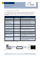
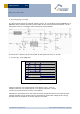
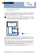
Table Of Contents
- 1 GENERAL DESCRIPTION
- 2 FUNCTIONAL DESCRIPTION
- 2.1 Simplified firmware flow chart and block diagram
- 2.2 Pin out
- 2.3 Pin description and operational characteristics
- 2.4 Absolute maximum ratings (non operating)
- 2.5 Maximum ratings (operating)
- 2.6 Power management and voltage regulators
- 2.7 Configuration
- 2.8 Radio telegram
- 2.9 Transmit timing
- 2.10 Charging circuitry
- 2.11 Energy consumption
- 3 APPLICATIONS INFORMATION
- 4 AGENCY CERTIFICATIONS

USER MANUA
L
V0.6
© 2010 EnOcean | www.enocean.com STM 31x / STM 31xC User Manual V0.6 | Page 20
/
28
STM 31X / STM 31XC
3 APPLICATIONS INFORMATION
3.1 Using the WAKE pins
The logic input circuits of the WAKE0 and WAKE1 pins are supplied by UVDD and therefore
also usable in “Deep Sleep Mode”. Due to current minimization there is no internal pull-up
or pull-down at the WAKE pins. When STM 31x is in “Deep Sleep Mode” and the logic levels
of WAKE0 and / or WAKE1 is changed, STM 31x starts up.
As the there is no internal pull-up or pull-down at the WAKE0 pin, it has to be en-
sured by external circuitry, that the WAKE0 pin is at a defined logic level at any
time. At time of delivery a jumper is connected between WAKE0 and UVDDext.
WAKE1 provides an internal 1.8 MΩ pull-up. See figure below.
When the LRN button is pressed WAKE1 is pulled to GND and a teach-in telegram is trans-
mitted. As long as the button is pressed a small current of approximately 1 µA is flowing. It
is possible to connect an additional external button in parallel between WAKE1 and GND if a
different position of the button in the device is required.
WAKE0 is connected to UVDDext via a jumper at time of delivery. If the module is mounted
onto a host PCB the jumper has to be removed. The circuitry on the host PCB then has to
ensure that WAKE0 is always in a defined position. There are two ways to use WAKE0:
Connect WAKE0 to UVDDext and connect an external button between WAKE0 and GND.
As long as the button is pressed a current of 1 µA will flow.
Connect a 3 terminal switch and switch WAKE0 to either GND or UVDDext. In this case
there is no continuous flow of current in either position of the switch.
EO3000I
WAKE0
WAKE1
UVDD
UVDDext
STM 31x
WAKE1
WAKE0
GND
1M8
1M8
LRN Button
Jumper installed at
time of delivery