
Enphase IQ System Controller 2 install guide


26
IQ System Controller 2 Quick Install Guide
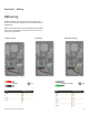
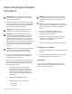
If PCS is being used place the following label on the deadfront with
the PCS setting lled in the blank space.
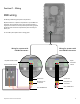
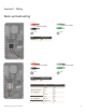
When installing a generator the Generator CT should be paralleld to
the Consumption CT wiring using a wago nut.
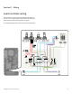
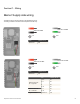
CT wiring
Section C - Wiring
There are multiple scenarios for CT wirings for a complete
description please refer to IQ Gateway QIG.
For PCS , whole home and complete home back up the
consumption CTs are to be placed as described in image
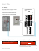
For PCS set up please refer to the Enphase installer APP.
After placing the Consumption CT and wiring to the IQ Gateway
the following label has to be pasted on the CT.
This sensor is part of a Power Control System. Do not remove
or disable. Replace with same type and rating.
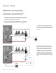
IQ Gateway Terminal Block
Not used
White
Blue
White
Blue
Relay contacts
(if needed)
CU, C, AWG MIN
MEAS CAT III
OVC III
PD, B
OVC II
NLL
P
Production
Digital Input
1234 NO
REF CCommon
Relay
Consumption
C C
THE MAXIMUM CURRENT BACKFED BY THIS SYSTEM TO THE MAIN PANEL
MAY BE CONTRTOLLED ELECTRONICALLY. REFER TTO MANUFACTURER’S
INSTRUCTIONS FOR MORE INFORMATION
PCS CONTROLLED CURRENT SETTINGS: AMPS