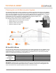
TECHNICAL BRIEF Planning for an IQ Microinverter System The Enphase IQ Microinverter system is inexpensive to install and provides a wide range of new installation options to solar professionals. The IQ Microinverter system is the ideal product for single-phase applications. New components available as part of this system provide additional options for reducing Balance of System (BOS) costs and installation complexity.
Planning for an IQ Microinverter System Q Cable and IQ Micro Accessories The IQ Microinverter system uses the new Q Cable with only two conductors, resulting in a more lightweight and flexible product. This UL3003 listed DG (Distributed Generation) cabling system is purpose designed for the application, and uses the following new accessories, which are not compatible with earlier Enphase cabling systems.
Planning for an IQ Microinverter System Specifying Cabling and Accessories at the Array The Enphase IQ Microinverter system uses a new and improved cabling system. The Q Cable is DG type and contains only two #12 AWG line conductors. The Q Cable male connectors plug directly into the IQ Micros, whose double insulation rating requires no neutral or ground conductors. This lightweight cable drives down system costs while simplifying installation.
Planning for an IQ Microinverter System You must install supports (clips, etc.) for the Q Cable and raw Q Cable at six-foot intervals or less. Installation requirements for wet-rated cable allow Q Cable and raw Q Cable to be installed in conduits, cable trays, and other raceways. The DG cable standard UL3003 is based upon the construction specifications (wet rated) of TC-ER cable, which may be installed in raceway as per NEC 336.10(3).
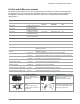
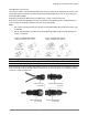
Planning for an IQ Microinverter System Field Wireable Q Connectors You can use the male or female Field Wireable Q Connectors to extend the Q Cable (with connectors) or the raw Q Cable (without connectors). Installers assemble the Field Wireable Q Connectors using a crimp tool and the provided terminals. Enphase recommends the Multi-Contact PV-CZM-18100, -19100, or -22100 crimp tools.
Planning for an IQ Microinverter System Sealing Caps You must seal each unused Q Cable connector with a watertight sealing cap (Q-SEAL). Male connector on Q Cable Female Sealing Cap (Q-SEAL) Seal each unused connector on the Q Aggregator with a male sealing cap. Also, during construction, you must use male sealing caps to temporarily seal any exposed IQ Micro connectors, that are not connected to the Q Cable, to protect against moisture or water damage at the exposed connector.
Planning for an IQ Microinverter System When using the Q Aggregator for combining multiple branch circuits on the roof, the combined production circuit cannot be terminated on any of the 20 A circuit breakers within the IQ Combiner.
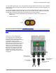
Planning for an IQ Microinverter System Design Considerations for the Q Aggregator The Q Aggregator: • Is a roof mounted combiner box, which supports up to three circuits. • Requires protection at the feeder panel by an over current protective device (OCPD) rated at an ampacity not to exceed 60A. Make sure the conductor size selected for field wire from Q Aggregator to the service connection is adequate for the OCPD chosen. • Allows for a single homerun back to the service of #12 to #4.
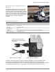
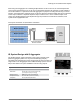
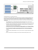
Planning for an IQ Microinverter System Branch Circuit 1 Branch Circuit 2 IQ Envoy in Enclosure Branch Circuit 3 Solar/ Envoy Subpanel Main Service Panel One 60A Homerun Circuit Installing IQ Envoy in an Outdoor Enclosure The IQ Envoy must be installed inside of an electrical enclosure, keeping the operating temperature of the Envoy in mind. This enclosure must be large enough to house the IQ Envoy and a dedicated receptacle to power the IQ Envoy.
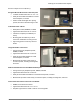
Planning for an IQ Microinverter System Enclosure Options for the IQ Envoy Arlington EB1212-BP Enclosure with back plate • Lockable unit dimensions are 12" x 12" x 4" • Easily accommodates the addition of a fieldwired receptacle, if needed • Outdoor rated with hinged door opening upward, but indoor rated with hinge to side Orbit 57905 Timer Cabinet • Back plate included, NEMA3R, lockable • Approximate dimensions are 11"x10"x5" • Includes a receptacle pre-installed (not wired) • Mounting plate
Planning for an IQ Microinverter System Field Wireable Q Connectors and Raw Q Cable The IQ Microinverter System makes complex installations simple. Field Wireable Q Connectors (Q-CONN-10F and Q-CONN-10M) and raw Q Cable (Q-12-RAW-300) allow a wide-range of installation options that are not available in DC systems or other microinverter systems.
Planning for an IQ Microinverter System Splicing Q Cable and Raw Q Cable with Junction Boxes For complex installations that include multiple arrays, it is possible to use raw Q Cable (Q-12-RAW-300) to service the arrays and branch circuits that do originate directly at the primary roof mounted junction box. In the case that Field Wireable Q Connectors are not readily available, a small junction box may be used to splice two sections of Q Cable together or may be used to splice Q Cable to raw Q Cable.
Planning for an IQ Microinverter System Example IQ Microinverter System Layouts and Bill of Materials (BOMs) Conceptual Image 13 © 2017 Enphase Energy Inc. All rights reserved.
Planning for an IQ Microinverter System Scenario 1: Simple 12 Module Scenario Bill of Materials for Scenario 1: Simple 12 Module Scenario QTY Part Number Description 12 IQ6PLUS-72-2-US 12 of 240 Q-12-10-240 Enphase IQ 6+ Microinverter, compatible with 60- and 72-cell PV modules, 290VA peak power, MC4 DC connectors, female AC connector Q Cable for 60/72 cell 1.0m portrait module pitch. Connector pitch is 1.3m.
Planning for an IQ Microinverter System Scenario 2: 24 Module, Two Strings of 12, Terminated at Junction Box Bill of Materials for Scenario 2: 24 Modules, Two Strings of 12 Terminated at Junction Box QTY Part Number Description 24 IQ6PLUS-72-2-US Enphase IQ 6+ Microinverter, compatible with 60- and 72-cell PV modules, 290VA peak power, MC4 DC connectors, female AC connector 26 of 240 Q-12-10-240 Q Cable for 60/72 cell 1.0m portrait module pitch. Connector pitch is 1.3m.
Planning for an IQ Microinverter System Scenario 3: 24 Module, Two Strings of 12, Terminated at Q Aggregator Bill of Materials for Scenario: 24 Modules, Two Strings of 12 Terminated at Q Aggregator QTY Part Number Description 24 IQ6PLUS-72-2-US 27 of 240 Q-12-10-240 x ft of 938 Q-12-RAW-300 Q Cable, 12 AWG, no connectors, 300m (984ft) length 2 of 10 Q-SEAL-10 Female sealing cap for unused Q Cable connectors. Pack of 10 3 of 10 Q-TERM-10 Q Terminator for Q Cable ends.
Planning for an IQ Microinverter System Wire Management of AC and DC Cables Under Array Since the Q Cable contains only two conductors, it is much smaller and lighter than the previous generation Engage Cable. For this reason, we use cable clips with a reduced wire retention area for the Q Cable. The outer dimensions of the Q Cable allow it to be supported by many of the existing PV cable clips and USE-2 cable clips that are frequently used for supporting the DC module leads today.
Planning for an IQ Microinverter System cabling on. Also, for AC Module installations, it is often more convenient to clip the Q Cable to the module frame than to clip the Q Cable to the racking system (if available). You must support the Q Cable and raw Q Cable at intervals not to exceed 6 feet and make sure that the cable does not touch the roof surface.
Planning for an IQ Microinverter System AC Wire Management at the Junction Box or Q Aggregator Wire management practices at the junction box are critical to the long-term reliability of any PV system. Installers often install the roof-mounted junction box on the side of a rail. If using the Q Aggregator, it must be installed underneath the modules. For Junction Box Applications Follow these recommendations to prevent moisture from accumulating in the junction box.
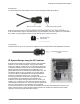
Planning for an IQ Microinverter System Installing IQ Microinverters with Frame Mount Bracket You can use the Enphase Frame Mount to attach the Enphase Microinverters directly to module frames. This may be the ideal solution for rail-less racking solutions, whether residential or commercial. When using the Enphase Frame Mount product, you can support the Q Cable to keep it off the roof by clipping it to the module frames using the same module edge wire clips that work with PV cable and USE-2 cable.
Planning for an IQ Microinverter System Specifications of Q-LCF-064 Filter • Shall be installed within a suitable enclosure. • Wire Enphase IQ Envoy/Micros on the load side and utility/site loads on the line side of the filter. • Wiring terminals accept #4 to #22 conductors • 250Vac / 64A maximum continuous inverter output current rating • Protect with maximum 80A overcurrent protection device (OCPD) • -25°C to 65°C • Recommended tightening torque of 2 to 2.
Planning for an IQ Microinverter System Mechanicals of Q-LCF-064 Filter (all dimensions in mm) 22 © 2017 Enphase Energy Inc. All rights reserved.