
Install Manual
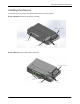
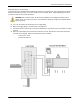
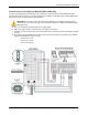
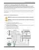
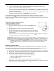
Table Of Contents
- SAFETY
- The Enphase Envoy-S
- Installation Planning and Preparation
- Installing the Envoy-S
- Activate Monitoring
- Envoy-S Operation
- Connecting to Envoy-S
- Troubleshooting
- Technical Data

Envoy-S Installation and Operation
2015 Enphase Energy Inc. 141-00027 Rev 01
16
Install CTs for Consumption Metering (Optional for Model ENV-S-AM1-120)
Install two split-core CTs (order two CT-200-SPLIT) to provide consumption metering. Create a protected
route with conduit for the CT wires from the main load center to the Envoy-S.
DANGER! Risk of electrocution! CTs must be installed with no current flowing in the sensed
circuit. Do not energize the sensed circuit until the CT leads are installed in the terminal block.
DANGER! Risk of electric shock. Be aware that installation of this equipment includes risk of
electric shock. If you wire the Envoy-S at the subpanel, it is a best practice to always de-
energize the main load center before beginning wiring. If the subpanel cannot be de-energized, a
qualified electrician may safely install the CTs as directed, making sure to connect the leads and
then place the CTs around each wire and latch.
WARNING! Do not install the CTs in a panel where they exceed 75% of the wiring space of any
cross-sectional area within the panel.
a. Make sure that the main load center wires are de-energized until you have secured the CT wires in
the terminal blocks. Before running the CT wires through the conduit, use colored tape to mark one
of the CTs and the free end of its wires.
b. For the marked CT wires, connect the white wire to “IA•” and the blue wire to “IA”.
c. For the unmarked CT wires, connect the white wire to “IB•” and the blue wire to “IB”.
d. Tighten the terminal block screws to 5 in-lbs.
e. Install the marked CT on the load center feed wire Line 1 (matching the Envoy’s “A” voltage terminal)
with the CT arrow pointing toward the breakers. Unlatch the CT, place Line 1 in through the opening.
Latch the CT and listen for the click as it closes.
f. Install the unmarked CT on the load center feed wire Line 2 (matching the Envoy’s “B” voltage
terminal) with the CT arrow pointing toward the breakers. Unlatch the CT, place Line 2 in through the
opening. Latch the CT and listen for the click as it closes.
Extend Consumption CT Leads, If Needed
If needed, an electrician may extend the leads of the consumption CTs using the following guidance:
WARNING! To extend the CT leads, the electrician must use appropriately rated, 18-14 AWG,
twisted pair wire and install it in accordance with all local electrical codes and the National Electrical
Code (NEC; NFPA 70).
The electrician may add as much as three ohms round trip resistance to the consumption CT or up to 1.5
ohms per wire. For reference, using NEC chapter 9 table 8 resistances, the following maximum lengths at
75° C by gauge are:
57.6 meters (189 feet) of 18AWG 7 strand Cu = 1.5 ohms
91.7 meters (301 feet) of 16AWG 7 strand Cu = 1.5 ohms
148.4 meters (478 feet) of 14AWG 7 strand Cu = 1.5 ohms
NEC chapter 9 table 8 resistance figures may not be appropriate for all geographies or installation
conditions. A licensed electrician should determine the wire gauge and type to obtain a maximum round trip
resistance of three ohms.