I NS TA L L A TI O N A N D O P E R A TI O N MA NU A L Envoy™ Communications Gateway 141-00011, Rev 03
Envoy Installation and Operation Contact Information Enphase Energy Inc. 201 1St Street Petaluma, CA 94952 http://www.enphase.com info@enphaseenergy.com support@enphaseenergy.com FCC Compliance This equipment has been tested and found to comply with the limits for a Class B digital device, pursuant to part 15 of the FCC Rules. These limits are designed to provide reasonable protection against harmful interference in a residential installation.
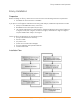
Envoy Installation and Operation Table of Contents Important Safety Information ................................................................................................................................ 4 Read this First ......................................................................................................................................... 4 Safety Instructions ............................................................................................................................
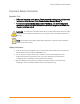
Envoy Installation and Operation Important Safety Information Read this First Follow the instructions in this manual. These instructions are key to the installation and maintenance of the Enphase Envoy Communications Gateway (Envoy™). To ensure the safe installation and operation of the Envoy, note the following safety symbols that appear throughout this document to indicate dangerous conditions and important safety instructions.
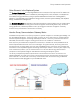
Envoy Installation and Operation The Enphase Envoy Communications Gateway The Envoy is an integral component of the Enphase Energy Microinverter system. It operates between the Enphase Microinverters and the Enphase Enlighten™ web-based monitoring and analysis software. The Envoy functions as a gateway and monitors the microinverters that are connected to the PV modules. The Envoy collects energy and performance data from the microinverters over in-home AC power lines.
Envoy Installation and Operation Other Elements in the Enphase System The Enphase Microinverter is a fully integrated device that converts the DC output of the PV module into electric-utility compliant AC power. In addition to performing the DC to AC conversion, it maximizes the PV modules' energy production by using a sophisticated Maximum Power Point Tracking (MPPT) algorithm.
Envoy Installation and Operation Envoy Installation Preparation Before installing the Envoy, make sure that the site meets the following minimum requirements: • Standard AC electrical outlet is available If you plan to use Enlighten web-based monitoring and analysis, additional requirements include: • Always-on broadband Internet connection • Broadband router with spare Ethernet port • Up-to-date web browser to view Enlighten. Supported browsers are Internet Explorer 8 or higher, Firefox 3.
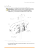
Envoy Installation and Operation Install the Envoy To install the Envoy, perform the following steps while referring to the diagram shown. BEST PRACTICE: When powered up and connected for the first time, the Envoy may retrieve an automatic upgrade from Enphase. Because this upgrade may take up to 45 minutes, connect the Envoy first at the site (connect to both AC power and the broadband router) so that it performs the upgrade well before the solar module installation is complete. 1.
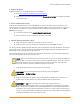
Envoy Installation and Operation 2. Register the Envoy Register the Envoy at the beginning of the PV installation. a. Visit http://enlighten.enphaseenergy.com/register. b. Register the site owner information and the Envoy serial number in the space provided in the online form. 3. Find a Location for the Envoy Enphase recommends that the Envoy be placed as close to the load center as possible. This ensures that the Envoy receives the strongest possible signal from each microinverter.
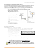
Envoy Installation and Operation 5. Connect Power Line Communication Bridges (Optional) If the Envoy needs to be located away from the router, at a distance where an Ethernet cable is not practical, use the power line communication bridges provided with the Envoy or purchase a wireless Ethernet bridge. Bridges allow the Envoy to communicate with the broadband router without the need for additional Ethernet cabling. To install the bridges: a.
Envoy Installation and Operation e. Assess the power line communications. To do this: • Wait until the Priority New Device Scan is complete (The message Priority Scan is Active will no longer be shown on the LCD). • Press and hold the Envoy menu button. Release it when the LCD window displays Enable Communication Check. The check will run for 20 minutes. • Note the number of bars shown in the Communication Check.
Envoy Installation and Operation 8. Build the Virtual Array When the system is energized and the Envoy detects all the installed microinverters, the installer can create the virtual array in Enlighten from the installation map they created. a. Log in to Enlighten. b. Use Array Builder to create the virtual array in Enlighten. c. Use your installation map as your reference. For more information, go to http://enphase.com/support/videos/ to see the Array Builder demo.
Envoy Installation and Operation Envoy Operation First Scan for Microinverters A newly installed Envoy automatically performs an initial scan to discover all of the microinverters that are installed and powered up at the site. This initial scan continues to search for new microinverters for seven days from initial start up of the Envoy. The purpose of this long scanning period is to account for additional microinverters that may be installed during this initial seven-day time frame.
Envoy Installation and Operation The normal, post installation boot sequence is shown: INITIALIZING [e] Enphase Energy Booting [||||||] Normal Boot Sequence Starting R3.0.0 2011/06/06 16:21:20 169.254.120.1 -Web 2407W 783kWh 25 Comm Check Searching... -Web 192.168.2.140 +Web 2407W 783kWh 25 [≡≡≡ ] Level mm:ss +Web Devices: 25 The last two screens alternate until the Communications Check ends, after 20 minutes.
Envoy Installation and Operation Normal Operation Once the Envoy completes a scan, it begins or resumes normal operation. At this point, the indicators in the LCD screen show current values for your system. This is the home screen: 192.168.2.140 +Web 2407W 783kWh 25 The data on the home screen may take a few minutes to appear after starting up the Envoy or initiating a scan. Information shown during normal operation includes: • Local IP address, for example: 192.168.2.
Envoy Installation and Operation 1. Press and hold this button; after two seconds you will see the Envoy menu in the Envoy’s LCD screen. 2. Continue holding the Menu button.
Envoy Installation and Operation Performing a Communication Check If, when you are installing the Envoy, you are unsure of where it should be located for maximum performance, you may want to install the Envoy in various locations and check signal strength. Normally, a communication check starts automatically after an Envoy restart.
Envoy Installation and Operation Above the “Level” indicator the LCD screen displays brackets enclosing zero to five bars. NOTE: Until microinverters are detected, the Level indicator shows no bars. Signal strength is acceptable if three to five bars are displayed and all devices are accounted for. One to two bars may not be effective for consistent communication. 3. If, after 15 minutes, fewer than three bars are displayed, refer to “Power Line Communication Troubleshooting” on page 24.
Envoy Installation and Operation The Envoy begins a 30-minute scan (if a longer scan is not already in progress) to identify all of the microinverters deployed at the site. 3. Use your previously issued username and password to check for the new microinverter in Enlighten. If you do not have a link to Enlighten, go to www.enphase.com and click Enlighten Login. From here you can register (if not already done) and view data on a per-microinverter basis (and, hence, a per-PV module basis). 4.
Envoy Installation and Operation If a grid profile has been applied, the following screens are displayed. You can press the menu button at any time to exit this process. (n) total devices (n)unsettable devices (n)devices are set with (local spec) (n)are propagating with (local spec) Number of microinverters detected. Number of microinverters that cannot be set with a grid profile. Number of microinverters that are set with a grid profile and the name of the specification being used.
Envoy Installation and Operation Enabling a Connection to Enphase The Enable Connection to Enphase menu item creates a secure connection to Enphase allowing Enphase personnel to troubleshoot the system remotely. Enable Connection To Enphase The LCD screen now reads: Enabling Connection Once the connection is open, the LCD will return to the default display. Disabling a Connection to Enphase The Disable Connection to Enphase menu item closes the secure connection to Enphase.
Envoy Installation and Operation 3. The Envoy LCD panel will scroll through the available locale settings. When you see the setting you need, press the Menu button and hold for two seconds. English Français Deutsch Italiano How the Envoy Works with Enlighten The Envoy operates between the Enphase Microinverters and the Enphase Enlighten web-based monitoring software.
Envoy Installation and Operation Networking and Firewall Info The Envoy communicates with the Enphase Enlighten website by initiating outbound TCP (Transmission Control Protocol) connections to Enphase over HTTPS (Hypertext Transfer Protocol over Secure Socket Layer) (TCP:443). The Envoy uses NTP (Network Time Protocol) (UDP:123) to periodically synchronize time/date with an external pool of NTP servers. You do not need to open any inbound firewall ports for normal operation.
Envoy Installation and Operation Troubleshooting The following sections describe possible problems and solutions. For information on system status and event messages, see “Event Messages” on page 38. For more extensive Troubleshooting information, refer to the manual, Troubleshooting an Enphase Installation at http://www.enphaseenergy.com/support/downloads. Power Line Communication Troubleshooting At power-up, the Envoy performs a “Communication Check”.
Envoy Installation and Operation Is the system energized? PV modules power microinverters, PV modules provide power only during daylight hours, and microinverters communicate only when powered. • Run another scan during daylight hours. • Check that the circuit breaker(s) for the PV array are in the “ON” position. For the Envoy to communicate with the microinverters, the PV circuit breakers must be in the “ON” position in the electrical load-center.
Envoy Installation and Operation Envoy Local Interface Connection to the Enphase Enlighten web-based monitoring and analysis software requires an Internet connection. However, if there is no Internet access at the installation site, it is still possible to communicate directly with the Envoy using the Ethernet port and a personal computer with a web browser. The following steps describe how to access the Envoy data through the local connection. 1.
Envoy Installation and Operation Production Screen To view system energy harvest statistics for your system, click Production from the Envoy home screen to navigate to the production screen. Inventory Screen To view a listing of the devices in your system, click Inventory from any screen to navigate to the inventory screen.
Envoy Installation and Operation Administration Screen The Administration screen of the Envoy local interface contains a number of configurable options. Click Administration to access this menu. NOTE: For Envoy performance reasons, Enphase does not recommend giving the Envoy a publicly accessible IP address. However, if you must place the Envoy on a public-facing IP address, Enphase recommends that you change the admin password to disallow unauthorized modification to your Envoy.
Envoy Installation and Operation Manage the Grid Profile Many Enphase microinverters have field adjustable voltage and frequency trip points. If adjustments are required by your local utility, when all microinverters have been detected, the installer can use the Envoy to Manage the Grid Profile. Each Grid Profile contains a set of trip points. Trip points are input voltage or frequency values that trigger the microinverters to shut down. These trip points vary from region to region.
Envoy Installation and Operation 3. From the Admin menu, select Device Grid Configuration. The Device Grid Configuration screen appears. This screen allows a licensed solar professional to select and apply the appropriate trip points for the solar installation. Click here to select a Country regulatory specification Click here to select a Grid trip point profile Enter your token here. Click here to Apply Profile 4. Select a Country regulatory specification. 5. Select a Grid profile. 6.
Envoy Installation and Operation 10. Enter the authorization number from the Envoy Interface. 11. Click Get Token. 12. Copy the token. 13. Paste or enter the token in the Grid Profile screen. 14. Click Apply Grid Profile. This step propagates the settings to the microinverters.
Envoy Installation and Operation 15. Click View Device Profile Report. Click here to View Device Profile Report The Device Profile Report screen appears 16. Enter the site information in the window provided. Enter site information here.
Envoy Installation and Operation 17. Use your browser to send this report to your printer or to save it to a file. After printing or saving the file, you can send it to the local regulatory agency to confirm the trip point settings. The report will look like the following example.
Envoy Installation and Operation Clear GFI Tripped Condition A solid red status LED on the microinverter indicates the microinverter has detected a ground fault (GFDI) error. The LED will remain red and the fault will continue to be reported by the Envoy until the error has been cleared. If a microinverter registers a GFI Tripped condition, you can attempt to clear this condition through the Envoy Interface.
Envoy Installation and Operation 3. In the clear-gfi box, select set. Select set Click Send Command 4. Click Send Command to complete this task. Device Scan Control The Controlled device scan differs from other Envoy device scans in that it allows control over scan period, scanning method, and number of devices. When first installed, the Envoy initiates a sevenday scan. This initial seven-day scan is the only scan needed for most systems.
Envoy Installation and Operation 3. Although optional, it is best practice to enter a value for Total Devices. Enter a value in this field. The Envoy will stop scanning once it has detected the given number of devices. NOTE: The Total Devices option can be used in conjunction with the Priority Duration option to help discover any last few microinverters at a large site. 4. Enter a Priority Duration (optional) in days:hours:minutes (e.g., 0:00:20 to indicate zero days, zero hours, and 20 minutes).
Envoy Installation and Operation Set the Time Zone If you do not have an Internet connection to the Envoy, you may want to set the local time zone on your Envoy. To set the Envoy time zone: 1. From the Admin menu, choose Date, Time, Time Zone. 2. Under Time Zone Setting, select a time zone from the Select Time Zone drop down menu. 3. Click Update timezone setting to complete this task. Other Admin Tasks • For information on optional Power Meter Configuration, see the Enphase PMRS Technical Brief.
Envoy Installation and Operation Event Messages The following table lists messages that the Envoy can produce to indicate certain conditions. These messages appear on screen when your computer is connected to the Envoy local interface. Where message is displayed: Home Screen Inventory Screen AC Frequency AC Frequency Changing Too Changing Too Fast Fast AC Frequency Out Of Range AC Frequency Out Of Range Description Recommended Action: No action is required unless the condition persists.
Envoy Installation and Operation Where message is displayed: Home Screen Inventory Screen AC Voltage Out AC Voltage Out Of Of Range Range Description Recommended Action: This condition should correct itself. No action is required. Description: The microinverter reports that the AC voltage coming from the utility is either too low or too high as specified by applicable regional standards.
Envoy Installation and Operation Where message is displayed: Home Screen Inventory Screen DC Resistance DC Resistance Low Low Description Recommended Action: No action is required unless the condition persists. Description: A sensor in the microinverter measures the resistance between the positive and negative PV inputs to ground. If either resistance drops below a threshold, the microinverter raises this condition.
Envoy Installation and Operation Where message is displayed: Home Screen Inventory Screen Envoy Failure Description Recommended Action: Unplug the Envoy from the electrical outlet and plug it in once again. Leave it plugged in and in place for at least 15 minutes. Description: This message displays after the Envoy has tried unsuccessfully three times to start up.
Envoy Installation and Operation Where message is displayed: Home Screen Inventory Screen Grid Gone Grid Gone Description Recommended Action: In most cases no action is required. If there is a power outage in your area and the system has stopped production, solar production will resume when the utility restores power to your area. Verify that the circuit breaker(s) for the PV array are ON at the load center. If all breaker(s) are on, the condition should clear itself.
Envoy Installation and Operation Where message is displayed: Home Screen Inventory Screen HardwareError HardwareError IUP Link Problem Description Recommended Action: Contact your installer to arrange for the installation of a replacement microinverter. Description: A hardware failure has occurred that prevents power conversion. Recommended Action: No action is required unless the condition persists.
Envoy Installation and Operation Where message is displayed: Home Screen Inventory Screen Microinverter grid configuration failed after 5 attempts, retrying Microinverter grid configuration failure cleared after xx attempts Description Module Sleeping Sleeping Description: The Microinverter is off for the night. No Grid Profile No Grid Profile Description: The attempt to change the grid profile for the microinverters has failed after five tries.
Envoy Installation and Operation Technical Data Communications Interface Power line Enphase proprietary Ethernet 10/100 auto-sensing, auto-negotiation USB (one or two ports, depending on Envoy model) USB 2.0 interface, auto-sensing, auto-negotiation Power Requirements AC outlet 120 VAC, 60 Hz Power consumption 2.5 watts typical, 7 watts maximum Mechanical Data Dimensions (WxHxD) 8.8” x 4.4” x 1.7” (222.5 mm x 112mm x 43.
Envoy Installation and Operation Appendix A — Limited Warranty Enphase Energy Inc. ("Enphase") has developed a highly reliable Envoy Communications Gateway that is designed to withstand normal operating conditions when used for its originally intended purpose in compliance with the Enphase User Manual supplied with the originally shipped system.
Envoy Installation and Operation • The returned Defective Product must not have been disassembled or modified without the prior written authorization of Enphase. The Enphase Envoy Communications Gateways are designed to withstand normal operating conditions and typical wear and tear when used for their original intent and in compliance with the installation and operating instructions supplied with the original equipment.
Enphase Energy Inc. Petaluma, CA 94952 www.enphase.com info@enphaseenergy.com support@enphaseenergy.