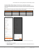
TECHNICAL BRIEF - North America Load and Solar Circuit Control using IQ System Controller Auxiliary Contacts Contents Load and Solar Circuit Control using IQ System Controller Auxiliary Contacts ................................. 1 Overview ................................................................................................................................................... 2 What are auxiliary contacts and how do they work? ........................................................................
Load and Solar Circuit Control using IQ System Controller Auxiliary Contacts Overview This document provides installers and design engineers with the information required to plan and configure Smart Control (load and solar circuit control) using IQ System Controller Auxiliary contacts.
Load and Solar Circuit Control using IQ System Controller Auxiliary Contacts Refer to the IQ System Controller QIG for installation instructions. Note: Use 3/32inch /2 mm flathead screwdriver to work on auxiliary contact terminals. Auxiliary contact usage Enphase recommends using Normally Open auxiliary contacts for solar and Normally Closed auxiliary contacts for loads.
Load and Solar Circuit Control using IQ System Controller Auxiliary Contacts Using the IQ Load Controller for load shedding The Enphase IQ Load Controller, when used in conjunction with the IQ System Controller smart switch, enables control of up to 2 loads or shedding of up to two solar circuits when operating in an off-grid mode with the Enphase energy management system. To install the IQ Load Controller, read and follow all warnings and instructions mentioned in the QIG provide with the product.
Load and Solar Circuit Control using IQ System Controller Auxiliary Contacts Note: The IQ Load Controller can also be used for shedding 4 loads running at 120Vac. If being used for such a use case it is important to ensure that the individual loads are connected on the outer poles of the contactors. Whenever possible, try to balance the current on the 2 poles of a contactor. To do this, connect the 2 loads with similar current requirements on the same contactor.
Load and Solar Circuit Control using IQ System Controller Auxiliary Contacts The above PV shedding wiring diagram is placed along with the QIG inside the enclosure of the IQ Load Controller. If setting up PV shedding on a site, it would be useful to stick this label over the load shedding wiring diagram stuck on the inner door of the enclosure. Follow all the instructions in the QIG provided with the product to setup PV shedding on a site.
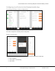
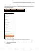
Load and Solar Circuit Control using IQ System Controller Auxiliary Contacts Configuring Load Control via the Enphase Installer App Accessing Auxiliary contact configuration Figure 4: Accessing Enphase Installer App Auxiliary Contact Configuration Press Site Configuration à Auxiliary Contact configuration Enable Load Control Figure 5: Configuring Load Circuit Control - Enable Load Control using Enphase Installer App 1. Press ‘Configure’ 2. Select option ‘Load Shedding’ 3.
Load and Solar Circuit Control using IQ System Controller Auxiliary Contacts Basic Mode: Shed load when off-grid IQ System Controller auxiliary contacts will shed the specific load circuits as soon as the system enters the off-grid mode. This is done to ensure that a stable microgrid is established. When the grid is back, the system will reconnect the load.
Load and Solar Circuit Control using IQ System Controller Auxiliary Contacts Scheduled Mode: When off-grid, shed loads at a certain time of the day In this mode, installer is provided the ability to set a certain time interval of the day when the connected loads would be powered when system is off-grid. At other times, if system is off-grid, these loads remain powered off. Note: If homeowner site does not have a battery installed, the allow time window to schedule load control is 9am to 4pm.
Load and Solar Circuit Control using IQ System Controller Auxiliary Contacts 3. Check ‘Home owner can override’ – this will let the home owner to access the settings from Enphase App Home Owner App 4. Press ‘Save’ Advanced Mode: Shed load when off-grid based on battery state of charge or generator availability This is an advanced mode allowing greater control over loads to the homeowner. Advanced mode can be used to control loads based on either battery or generator.
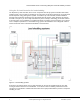
Load and Solar Circuit Control using IQ System Controller Auxiliary Contacts Figure 8: Battery Mode: Load control based on ESS State of Charge (SoC) via Enphase Installer App Select ‘Advanced’ Select ‘Battery’ as the ‘Off Grid power Source’ Select the required SoC limit using the sliding range selector Select the Buffer value. Check ‘Homeowner can override’ – this will let the homeowner to access the settings from Enphase App Homeowner App 6. Press ‘Save’ 1. 2. 3. 4. 5.
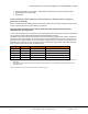
Load and Solar Circuit Control using IQ System Controller Auxiliary Contacts Mode MID GID on-grid off-grid off-grid Closed Open Open Open Open Closed Load circuit state Connected Disconnected Connected Table 4: Automatically shed load when off-grid and restore when generator is connected Figure 9: Generator Mode: Shed load when off-grid and restore when generator is connected 1. In ‘Advanced’ Mode, Select ‘Generator’ under ‘Off Grid Power Source’ 2.
Load and Solar Circuit Control using IQ System Controller Auxiliary Contacts Manual Mode: Keep the load permanently on or off irrespective of grid availability. In this mode, loads retain their defined state permanently irrespective of the presence of the grid. A load that is selected to be powered on remains on and a load that is selected to be powered off remains off. Figure 10: Manual mode 1. Select ‘Manual’ mode 2. Select whether to keep the load always powered or always switched off. 3.
Load and Solar Circuit Control using IQ System Controller Auxiliary Contacts Automatically shed solar circuit when off-grid IQ System Controller auxiliary contacts will shed specific PV circuits from the microgrid to ensure that the solar to storage continuous power ratio is maintained at a safe level.
Load and Solar Circuit Control using IQ System Controller Auxiliary Contacts Disable PV shedding Figure 12: Automatically shed PV circuit when off-grid - Disable PV shedding 1. Select the relevant Auxiliary Contact 2. Click ‘Disable’ button on the bottom of the screen 3. Confirm ‘Disable’ option in the pop up Validation of auxiliary contacts using Enphase Installer App Figure 13: Validation of auxiliary contacts - 1 15 © 2021 Enphase Energy Inc. All rights reserved.
Load and Solar Circuit Control using IQ System Controller Auxiliary Contacts 1. Click “Start Auxiliary Contact Validation” Figure 14: Validation of auxiliary contacts -2 Figure 15: Validation of auxiliary contacts -3 16 © 2021 Enphase Energy Inc. All rights reserved.
Load and Solar Circuit Control using IQ System Controller Auxiliary Contacts Figure 16: Validation of auxiliary contacts -4 1. 2. 3. 4. Press “Validate” Press “Disconnect the PV” If the production value goes down press “Yes” If production value goes down, validation is successful Figure 17: Validation of auxiliary contacts -5 17 © 2021 Enphase Energy Inc. All rights reserved.
Load and Solar Circuit Control using IQ System Controller Auxiliary Contacts Figure 18: Validation of auxiliary contacts -6 1. 2. 3. 4. Press “Validate” Press “Disconnect load” If the load is powered down validation is successful If the load is not powered down the validation is not successful Troubleshooting steps Test Expected Observation Implication 1. Open the breaker connected to the power supply input. 2. Use voltmeter to test the terminals of the contactor. 3. Close the load breaker.
Load and Solar Circuit Control using IQ System Controller Auxiliary Contacts Basic Mode: Shed load when off-grid In this mode, the load is switched off as soon as the system goes off-grid. Figure 19: Basic Mode in Enphase App: Shed load when off-grid 1. Select radio button ‘Basic Mode’ 2. Press ‘Apply’ Scheduled Mode: When off-grid, shed loads at a certain time of the day.
Load and Solar Circuit Control using IQ System Controller Auxiliary Contacts Figure 20: Scheduled Mode in Enphase App: Load control based on ESS State of Charge (SoC) 20 © 2021 Enphase Energy Inc. All rights reserved.
Load and Solar Circuit Control using IQ System Controller Auxiliary Contacts 1. Select radio button ‘Scheduled’ 2. Select time of the day at which the load is to be shed. 3. Press ‘Apply’ Advanced Mode: Shed load based on battery state of charge or generator power availability. This is an advanced mode allowing greater control over loads to the homeowner. Advanced mode can be used to control loads based on either battery or generator.
Load and Solar Circuit Control using IQ System Controller Auxiliary Contacts Figure 22: Generator Mode in Enphase App: Shed load when off-grid and restore when generator is connected 1. Select radio button ‘Advanced’ 2. Select radio button ‘Generator’ 3. Press ‘Apply’ Manual Mode: Keep the load permanently on or off irrespective of grid availability. In this mode, loads retain their defined state permanently irrespective of the presence of the grid.
Load and Solar Circuit Control using IQ System Controller Auxiliary Contacts Figure 23: Manual Mode in Enphase App: Shed load when off-grid and restore when generator is connected 1. Select radio button ‘Manual’ 2. Toggle between the 2 options: ‘Not Powered’, ‘Powered’ 3.
Load and Solar Circuit Control using IQ System Controller Auxiliary Contacts Figure 24: IQ System Controller Auxiliary contact wiring diagram The line diagram represents both the Normally Opens auxiliary contacts configured for PV shedding and load shedding. Refer Appendix A for detailed Single line diagram. Supported Contactors and transformers Definite purpose Contactors must meet or exceed the following parameters to work with IQ System Controller.
Load and Solar Circuit Control using IQ System Controller Auxiliary Contacts Square D Square D 8910DP32V14 8910DPA63V14 30 60 2 pole, NO 3 pole, NO 24 Vac 24 Vac Table 8: Supported contactors Supported transformers (for power supply) Supplier Part Number Secondary Voltage Fiada B07RDBS6NK 24 Vac Endurance Pro EP4031OF 24 Vac Primary Voltage VA Rating 120/208/240Vac 120/208/240Vac 40 40 Table 9: Supported Transformers for power supply Recommended fuses and fuse holders 1.
Load and Solar Circuit Control using IQ System Controller Auxiliary Contacts Example Wiring: Heavy 240V Load Shedding for 1X Circuit Figure 25: Example Wiring: Heavy 240V Load Shedding for 1X Circuit Using an external contactor with a 120Vac coil 24 Vac coil based definite purpose contactors for large loads typically have holding currents that exceed IQ System Controller auxiliary contact rating of 1 A.
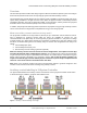
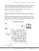
Load and Solar Circuit Control using IQ System Controller Auxiliary Contacts IQ Combiner Mobile connect IQ6/7 Microinverters Wireles s comms ENVOY Shed PV To utility grid 120/240V single phase service only Wireless comms N Contactor w/ 120Vac Coil IQ Autotransfor combiner mer Back up load panel ` Encharge Generator NC1 AC to DC Power Supply N NO Legend Enpower 200G COM Power Relay w/ 12Vdc Coil Power line Auxiliary contact wiring 12Vdc Note: • NC1 – Normally Closed auxiliary contacts u
Load and Solar Circuit Control using IQ System Controller Auxiliary Contacts Reference BOM for 120 A load or PV shedding circuit Item Description Quantity DC power supply 12V 1A APV-12-12 Meanwell AC-DC Switching Power Supply 1 Power Relay Schneider Electric Relays W9AS5D52-12 1 Contactor 120A Contactor C25HNE3120A Eaton / Cutler Hammer • 3 Pole • 110/120V Coil QILIPSU Hinged Cover Stainless Steel Latch Junction Box with Mounting Plate, ABS Plastic DIY Electrical Project Case IP67 Waterproof Dust
Load and Solar Circuit Control using IQ System Controller Auxiliary Contacts Example wiring: PV shedding using definite purpose contactor with 120 Vac coil Figure 29 Example wiring: PV shedding using definite purpose contactor with 120 Vac coil Please refer to Appendix C for more wiring configurations. 29 © 2021 Enphase Energy Inc. All rights reserved.
Load and Solar Circuit Control using IQ System Controller Auxiliary Contacts Validation and Troubleshooting Guidelines for setting up a custom Load Control kit Install Validation 1. Ensure control transformer is wired correctly. a. Confirm that there is 120 Vac to primary with appropriate fusing. b. Confirm that there are no shorts on the secondary c. Confirm that there are 24 Vac on the secondary. d. Important: never wire 120 Vac to the auxiliary contactors on IQ System Controller.
Load and Solar Circuit Control using IQ System Controller Auxiliary Contacts Step Symptom 4 Contactor is under powered. Diagnosed by measuring AC voltage on contactor coil. 5 Contactor does not open when expected. Possible cause Contactor produces loud buzzing and there is no voltage on load side (not closed.
Load and Solar Circuit Control using IQ System Controller Auxiliary Contacts Appendix A: Single Line Diagram Figure 30 Detailed Single Line Diagram 32 © 2021 Enphase Energy Inc. All rights reserved.
Load and Solar Circuit Control using IQ System Controller Auxiliary Contacts Appendix B: Controlling air conditioning unit using a thermostat.
Load and Solar Circuit Control using IQ System Controller Auxiliary Contacts Appendix C: Recommended maximum distance between IQ System Controller and IQ Load Controller. The System Controller sends a 24VDC signal from the aux contact to the load controller. The DC power source inside the load controller takes power from the back up panel (120V AC). There will be a voltage drop across both these cables in account of the inherent resistance of the cables.
Load and Solar Circuit Control using IQ System Controller Auxiliary Contacts This calculation is assuming that the wire resistance as mentioned in the tables above. With increased wire resistance the distance will reduce further. To compute for a different wire resistance please use the below formulae 𝑁𝑒𝑤 𝐷𝑖𝑠𝑡𝑎𝑛𝑐𝑒 = (𝑂𝑙𝑑 𝑑𝑖𝑠𝑡𝑎𝑛𝑐𝑒 (𝐴 𝑜𝑟 𝐵) ∗ 𝑁𝑒𝑤 𝑟𝑒𝑠𝑖𝑠𝑡𝑎𝑛𝑐𝑒) ÷ 21 What happens when the distance exceeds the recommendation? • • Contactors and power source don’t get adequate voltage to startup.
Load and Solar Circuit Control using IQ System Controller Auxiliary Contacts 2. Reference BOM for 2 x 40A load/PV control Quantity Component Box Box internal mounting plate Contactor Control Transformer Fuse Fuse Holder Quick Disconnects Fork connector Fork connector 36 Description Part Number WH-22 Hinged Nema Outdoor Enclosure(13.74 x 9.82 x 5.88 in) WH-22K Panel for WH-22 Enclosures(12.51 x 8.58 x 0.
Load and Solar Circuit Control using IQ System Controller Auxiliary Contacts 3 Wing nut Splicing connector Screws Feed Through Header Winggard Twist-On Wire Connector 13-086 Gardner Bender Wago Nut Screws to hold components in place (Grabber #8 x 9/16 in. 14mm Waferhead Screw) 221-413 Wago 31ZV Grabber 3 10 2 Pluggable Terminal Blocks 4 Pos 3.81mm pitch Plug 28-16 AWG Screw 1828362 Phoenix Table 14: 40A load shedding BOM 2 3.
Load and Solar Circuit Control using IQ System Controller Auxiliary Contacts Example Wiring 2x Solar Circuits using 30A contactors for Excess Solar Shedding Figure 32: Example Wiring 2x Solar Circuits using 30A contactors for Excess Solar Shedding 4.
Load and Solar Circuit Control using IQ System Controller Auxiliary Contacts Example Wiring: Excess Solar Shedding for 1 Branch Circuit Figure 33: Example Wiring: Excess Solar Shedding for 1 Branch Circuit Reference Wiring Image 39 © 2021 Enphase Energy Inc. All rights reserved.
Load and Solar Circuit Control using IQ System Controller Auxiliary Contacts 40 © 2021 Enphase Energy Inc. All rights reserved.