
IQ Load Controller Additional Info
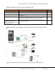

Load and Solar Circuit Control using IQ System Controller Auxiliary Contacts
24 © 2021 Enphase Energy Inc. All rights reserved. December 16, 2021
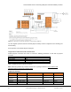
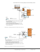
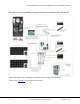
Figure 24: IQ System Controller Auxiliary contact wiring diagram
The line diagram represents both the Normally Opens auxiliary contacts configured for PV shedding and
load shedding.
Refer Appendix A for detailed Single line diagram.
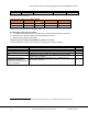
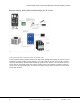
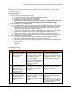
Supported Contactors and transformers
Definite purpose Contactors must meet or exceed the following parameters to work with IQ System
Controller.
Parameter
Value
Continuous Current
< 1 A
Coil Voltage
24 V
Inrush VA
40 VA or rating of transformer being used
Opening time
≤ 30 ms
Table 7: Definite purpose contactor parameters
Note: Follow all guidelines by contactor manufacturer regarding installation. Ensure that the load
connected does not exceed the contactor rating.
Supported contactors
Supplier
Part Number
Full Load Amperage (A)
Poles & NO/NC
Coil Voltage
Eaton
C25BNB220T
20
2 pole, NO
24 Vac
Cutler-
Hammer
C25BNF240T
40
2 pole, NO
24 Vac
Protactor
PT-C240A
40
2 pole, NO
24 Vac
Packard
L45-038 C240A
40
2 pole NO
24Vac
Eaton
C25FNF260T
60
2 pole, NO
24 Vac