
IQ Load Controller Additional Info


Load and Solar Circuit Control using IQ System Controller Auxiliary Contacts
34 © 2021 Enphase Energy Inc. All rights reserved. December 16, 2021
Appendix C: Recommended maximum distance between IQ System
Controller and IQ Load Controller.
The System Controller sends a 24VDC signal from the aux contact to the load controller. The DC power
source inside the load controller takes power from the back up panel (120V AC). There will be a voltage
drop across both these cables in account of the inherent resistance of the cables. It is essential to ensure
that the cable length selected is such that the voltage drop across both the lines (IQ System Controller-IQ
Load controller and Back up Panel to IQ Load Controller ) is within the limit of the contactor and the
power source.
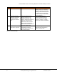
The technical data for the products used in the load controller are as below:
Devices on Backup panel-IQ Load Controller line
S.No
Parameter
Value
1
Voltage
120VAC
2
Max Current (in rush of power source)
25A
3
Min possible voltage for load center to operate
85VAC
4
Max permissible voltage drop
35VAC (120-85)
3
Wire Gauge used
18AWG
4
Resistance of wire gauge (average)
21 Ohm/1000 m
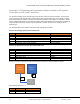
Devices on IQ System Controller-IQ Load Controller line
S.No
Parameter
Value
1
Voltage
24VDC
2
Max Current (in rush of contactor)
2 A
3
Min possible voltage for load center to operate
20.4 VDC
4
Max permissible voltage drop
3.6 VDC (24-20.4)
3
Wire Gauge used
18AWG
4
Resistance of wire gauge (average)
21 Ohm/1000 m
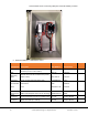
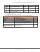
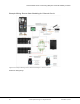
Based on the above values the recommended distance between the devices will be as follows
Max possible values for A and B are as follows
Sr.No
Component
Max. Distance (in ft)
1
A
100
2
B
135
System
Controller
Back up
panel
Load
controller
A
B