
IQ Load Controller Additional Info


Load and Solar Circuit Control using IQ System Controller Auxiliary Contacts
35 © 2021 Enphase Energy Inc. All rights reserved. December 16, 2021
This calculation is assuming that the wire resistance as mentioned in the tables above. With increased
wire resistance the distance will reduce further. To compute for a different wire resistance please use the
below formulae
𝑁𝑒𝑤 𝐷𝑖𝑠𝑡𝑎𝑛𝑐𝑒 =
(
𝑂𝑙𝑑 𝑑𝑖𝑠𝑡𝑎𝑛𝑐𝑒
(
𝐴 𝑜𝑟 𝐵
)
∗ 𝑁𝑒𝑤 𝑟𝑒𝑠𝑖𝑠𝑡𝑎𝑛𝑐𝑒
)
÷ 21
What happens when the distance exceeds the recommendation?
• Contactors and power source don’t get adequate voltage to startup. This leads to ‘Chattering’ of
the contactor, which is a high frequency ON/OFF of contactors. This leads to damage to the
contactor if this state prolongs for a long time.
• The system experiences the inrush current for a longer period of time, which can lead to potential
damage to the IQ System Controller and to the cables if this state is allowed to persist for long.
Due to the above-mentioned reasons, it is highly recommended to mount the Load controller is installed
within the distances recommended from the System Controller and Back up Panel.
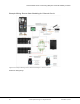
Appendix D: Additional reference BOM configurations
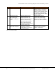
1. 40A Load Shedding
Item
Description
Units Required
Purchase Link
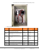
Enclosure
Gratury 15.7” *11.8” junction box
1
Link
Power Supply
Fiada (B07RDBS6NK) control
transformer
1
Link
Definite Purpose
Contactor
Packard(C240A) 24Vac 40A coil
1
Link
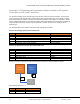
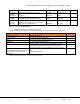
Fuse Holder
Parts Express(3AGAGC) Screw
Terminal Fuse holder
1
Link
Fuse
Bussman (BP/AGC-1-RP) 1A 250V
glass fuse
1
Link
Wiring
Gardner Bender(AMW-318) #18 Single
Strand Wire
As required
Link
Table 13: 40A Load shedding BOM