IQ System Controller 2 Quick Install Guide M O D E L NUMB ERE P2 0 0G 101- M 240US01 V E R S I O N 8.
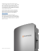
The Enphase Energy System includes the Enphase IQ System Controller 2 with Microgrid Interconnection Device (MID) capability, which consolidates interconnection equipment into a single enclosure and streamlines grid-independent capabilities of PV and storage installations by providing a consistent, pre-wired solution for residential applications. Along with MID functions, it includes PV, storage, and generator input circuits.
Table of contents Scenario 1 Whole home back-up with IQ System Controller 2 Scenario 2 Partial home back-up with IQ System Controller 2 Section C Wiring Drill conduits DER wiring Aux wiring: Rapid shutdown switch Scenario 2A Partial home backup with Sunlight Backup Aux wiring: IQ Load Controller Aux wiring: Generator control What’s in the box Tools / Additional items required Mains / Supply side wiring Back-up loads wiring CT wiring Section A Mounting the product Plan a location for the IQ System Con
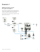
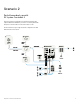
Scenario 1 Whole home back-up with IQ System Controller 2 This is the preferred configuration for back up of the entire main load panel. This configuration supports up to an 80A breaker each for the PV circuit, battery storage and Generator(optional). The microinverters ranges supported in this configuration are IQ8, IQ6/7, M-Series and S-Series.
Scenario 2 Partial home back-up with IQ System Controller 2 This is the preferred configuration for partial home backup with subpanel with PV and IQ Battery. Generator can be integrated with IQ System Controller 2 based on the homeowner’s needs. The microinverters ranges supported in this configuration are IQ8, IQ6/7, M-Series and S-Series.
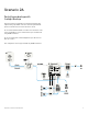
Scenario 2A Partial home backup with Sunlight Backup This is the preferred configuration for partial home backup with subpanel using only IQ8 PV. Generator can be integrated with IQ System Controller 2 based on the homeowner’s needs. It is recommended that installers use 2 IQ Load Controllers in order to do load shedding to ensure seamless back up of essential loads using IQ8 Microinverters. It is not recommended to install sunlight back up for whole home back up scenarios.
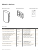
What’s in the box IQ System Controller 2 Wall Mounting Bracket Rapid Shutdown Switch Accessory kit ITEM NAME I T E M C AT E G O R Y PAT H DESCRIPTION QUANTITY Filler Cover Mounting BKT-L 200G Enpower Plastic Part Filler Cover Mounting BKT-L 200G IQ System Controller 2 Filler Cover Mounting BKT-R 200G Enpower Plastic Part Filler Cover Mounting BKT-R 200G IQ System Controller 2 Screw, Pan Hd , Phillips #3, M6x25mm Lg (5mm Shank - 20mm Thread), Machine, 304 SS Fastener Screw, Pan Hd , Phill
Tools / Additional items required S.
Section A Mounting the product Plan a location for the IQ System Controller 2 +50°C -40°C IQ System Controller 2 Quick Install Guide • It is recommended to install the product indoors, if the product is installed outdoors it is recommended to be installed where there is no direct exposure to sunlight. • Install this product on the place where PV cables, smart meter cables, grid cables and battery cables are easily accessible. • This product is designed to be installed on the wall vertical only.
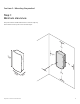
Section A - Mounting the product Step 1: Minimum clearance This product must be installed wth clearance at the left, right, top, bottom and front of the product as shown in the figure.
Section A - Mounting the product Step 2: Installing the mounting bracket Installing the mounting bracket and mount the IQ System Controller 2 as per instructions below. Please note the following before installing 1. 2. 3. Risk of injury and equipment damage. Do not release the IQ System Controller 2 until you ensure that the IQ System Controller 2 is fully seated in the wall-mount bracket shelf. The IQ System Controller 2 smart switch weighs 39.
Section A - Mounting the product Step 3: Open the dead front 1 Before removing the deadfront , ensure the IQ System Controller 2 is completely de-energized. Please note the following 1. Risk of equipment damage. Do not remove the pre-installed solar shield attached to the enclosure door. 2. Risk of electric shock. To maintain the warranty, do not modify the deadfront other than to remove or replace filler plates, as needed.
Section B Mounting the breakers Internal schematic of IQ System Controller 2 Once the deadfront is removed the IQ System Controller 2 looks as below. It comes with an inbuilt neutral forming transformer, microgrid interconection device , automatic transfer switch and a panel board to mount plug in type breakers.
Section B - Mounting the breakers Wiring for service entrance If the IQ System Controller 2 is used as a service entrance equipment Grounding Electrode Terminal • Do not remove the green colored ground neutral jumper • Paste Labels provided in Accessory Kit Grounding Electrode Terminal Main/Service Disconnect Suitable for use as Service Equipment Main/Service Disconnect Suitable for use as Service Equipment If the IQ System Controller 2 is NOT used as a service entrance equipment • Remove the Grou
Section B - Mounting the breakers Install main and back-up breakers If breakers are being installed for mains and back up connections the lugs should be removed and the breakers should be installed. ENPHASE BREAKER SKU E ATO N B R E A K E R PA R T BRK-100A-2P-240V CSR2100N Before wiring the breaker ensure the IQ System Controller 2 is completely De-energized. BRK-125A-2P-240V CSR2125N BRK-150A-2P-240V CSR2150N Only Eaton CSR range breakers with ratings between 100-200A can be used.
Section B - Mounting the breakers Installing DER breakers for IQ8 Systems without Generator The IQ System Controller 2 comes pre-installed with a 40A breaker for the neutral forming transformer (NFT) . When a generator is not being installed theNFT breaker need not be disturbed.
Section B - Mounting the breakers Installing DER breakers for IQ8 Systems with Generator IQ System Controller 2 allows for generator integration with the Enphase Energy Systems. The breaker on the bottom right slot can be sized and used to integrate the geenrator. For wiring schematic on Generator control and wiring the power lines from generator the subsequent section of installation guide.
Section B - Mounting the breakers Installing DER breakers for non IQ8 Systems The IQ System Controller 2 comes pre-installed with a 40A breaker for the neutral forming transformer (NFT) . When a generator is not being installed theNFT breaker need not be disturbed.
Section C Wiring Drill conduits Drill conduit entry holes as needed, and install conduit grounding lugs for each opening. Be sure to reseal unused conduit entry holes with sealing plugs. NOTE: Main supply conductors may enter the IQ System Controller 2 from the bottom or from the bottom-left side. Backup load conductors may enter the IQ System Controller 2 from the bottom or bottom-right side. IQ Batery, IQ Combiner and generator conductors may enter from the bottom, bottom-left or bottom-right sides.
Section C - Wiring DER wiring The DERs (IQ Battery, AC Combiner/Solar and generator) wires need to be connected to the lugs at the bottom as indicated in the images below. Before connecting the wires refer the wiring table recommendation and torque recommendation and also refer to local codes for any specific local requirements. Battery wiring PV wiring 2-14 AWG Generator wiring 1/8’’ 300KCMIl to 14 AWG AW G TO R Q U E ( L B . I N ) 1/0 - 3 50 AW G TO R Q U E ( L B .
Section C - Wiring Aux wiring: Rapid shutdown switch Aux Wiring 1: RSD wiring (Compliance requirement) Rapid shutdown is a compliance requirement as per the NEC and the UL1741. This is needed in order to ensure that there will be a single point shutdown for all solar panels. Enphase Energy System Shutdown meets the future requirements by disconnecting the battery too.
Section C - Wiring Aux wiring: IQ Load Controller IQ Load Controller is a feature of the IQ System Controller 2 which can be used to control upto 4x 240V loads or 8x 120V loads. At least one IQ Load Controller is needed for Sunlight Back-up systems. For a detailed wiring instruction refer to the IQ Load Controller QIG NOTE: Supports AWG 28 to AWG 16 wire sizes.
Section C - Wiring Aux wiring: Generator control An auto-start generator can be integrated with the Enphase Storage system without the need for any external ATS. 1. Install a pair of generator CTs (CT-200-SPLIT) for L1 and L2 at the IQ System Controller 2 Generator input terminal for power monitoring when the generatoris running. 2. Use Enphase Installer Toolkit mobile application to commission and program IQ System Controller 2 to control the generator.
Section C - Wiring Mains / Supply side wiring The mains wiring is to be the final step in the installation process. The wiring is similair for both full home and partial home back up. 300kcmil to 14 AWG 300 kcmil-2 AWG 1/4’’ 3/8’’ AW G TO R Q U E ( L B . I N ) 300kcmil-2 250 300 kcmil to 14 AWG 300 kcmil-1/0 AWG 1/4’’ 3/8’’ AW G TO R Q U E ( L B . I N ) 300kcmil-2 275 AW G TO R Q U E ( L B .
Section C - Wiring Back-up loads wiring 300kcmil to 14 AWG 300 kcmil-2 AWG 1/4’’ 3/8’’ AW G TO R Q U E ( L B . I N ) 300kcmil-2 250 300kcmil to 14 AWG 300 kcmil-1/0 AWG 1/4’’ 3/8’’ AW G TO R Q U E ( L B . I N ) 300kcmil-2 275 AW G TO R Q U E ( L B .
Section C - Wiring CT wiring There are multiple scenarios for CT wirings for a complete description please refer to IQ Gateway QIG.
Close and energize IQ System Controller 2 WARNING! At commissioning, you must reconnect the AC combiner L1 and L2 circuits back to the terminal lugs in IQ System Controller 2 as shown in step 5(F) in this document. WARNING: Before energizing, make sure that All IQ System Controller 2 connections are properly installed and conductors terminated. A. Reconnect the deadfront ground cable to the grounding bar, torque as shown in the start of the guide, and replace the deadfront using the 5 reserved screws.
Safety IMPORTANT SAFETY INSTRUCTIONS. SAVE THESE INSTRUCTIONS. This guide contains important instructions that you must follow during installation and maintenance of the Enphase IQ System Controller 2. Failing to follow any of these instructions may void the warranty (enphase.com/warranty).
IQSC-2-IG-0051-01-EN-US-2022-10-21 © 2022 Enphase Energy. All rights reserved. Enphase, the Enphase logo, IQ8 Microinverters, and other names are trademarks of Enphase Energy, Inc. Data subject to change.