
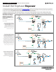
Enpower Load Center Install Guide

ONON
ONON
80
max
80
max
40
40
80
max
80
max
60
max
60
max
ON
80
max
80
max
40
40
80
max
80
max
60
max
60
max
AC Combiner
Neutral
Transformer
GeneratorEncharge
ON
80
max
80
max
40
40
80
max
80
max
60
max
60
max
AC Combiner
Neutral
Transformer
GeneratorEncharge
Mains
Breaker
200A max
Load
Breaker
200A max
I/O-1
I/O-2
Gen I/O
Mains
Relay
Mains
Relay
Neutral
AC Combiner /
Encharge / Generator
Main / Service
Disconnect
ON
AC Combiner
Encharge
Generator
ON
80
max
80
max
40
40
80
max
80
max
60
max
60
max
AC Combiner
Auto
Transformer
GeneratorEncharge
Mains
Breaker
200A max
Load
Breaker
200A max
I/O-1 I/O-2 Gen-I/O
Mains
Relay
Neutral
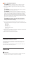
Main Bonding Jumper.
Remove when not required
Backup
Loads
I/O-1 / I/O-2 /
Gen I/O
Grounding Electrode
Conductor, when required
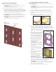
Wire the Field Connections
A ) Drill conduit entry holes as needed, and install conduit grounding lugs for each opening. Be sure to reseal unused conduit entry holes with sealing plugs.
NOTE: Main supply conductors may enter the Enpower from the bottom or from the bottom-left side. Backup load conductors may enter the Enpower
from the bottom or bottom-right side. Encharge, Combiner and generator (future) conductors may enter from the bottom, bottom-left or bottom-right
sides.
B ) Size the conductors (Line, Neutral and Ground) depending on the breaker or fuse, proper ampacity, and voltage rise requirements according to local codes.
Refer to the conductor rating table on the door of the Enpower.
+ DANGER! Risk of electric shock. Check that all circuits connecting to the Enpower are de-energized before wiring.
C ) If the Enpower is not installed at service equipment, you must remove the main bonding jumper connected between the grounding bar and the neutral
assembly. Refer to the wiring diagram.
NOTE: Do not modify or rewire any of the other pre-installed wiring or bonding connections in the Enpower.
D ) If Enpower is installed as service equipment:
•
Connect a grounding electrode conductor to the grounding bar.
•
From the literature kit, place the label “GROUNDING ELECTRODE TERMINAL” adjacent to the grounding bar.
•
From the literature kit, place the label “SUITABLE FOR USE AS SERVICE EQUIPMENT” on the deadfront near the main breaker/service disconnect.
•
From the literature kit, place the label “MAIN/SERVICE DISCONNECT” on the deadfront near the main breaker/service disconnect.
•
If Enpower is not used as service equipment:, these labels should not be used.
E ) Connect Lines, Neutral, and Ground. For details, refer to the conductor table on the unit for sizes and refer to local codes.
* WARNING! Risk of equipment damage. Always connect to two Lines (active),
one neutral, and one ground.
F ) Use the included stowed conductors, as labeled, to wire the circuit breaker(s) for
the Encharge batteries, Enphase Combiner, and generator (future), as needed. The
stowed conductors are provided with crimped-on ferrules with end caps to prevent
accidental contact. Remove the conductor end caps as needed.
G ) Torque the breaker connections as listed on the previous page and in the conduc-
tor table on the unit.
H ) After all conductors are connected and secured, check that there are no exposed
conductors or stray wires.
I ) Gently arrange all the conductors and connectors inside the cabinet.
+
DANGER! Risk of electric shock. The system is not ready to be energized! Do
not close any circuit breaker yet.
5
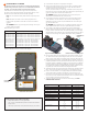
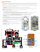
Conduit guidance -
bottom entry
Conduit guidance -
side entry
AC power wire
Stowed conductors
for generator (future)
Control PCBA and cover
Auto transformer/NFT
Breakers for auto transformer,
generator, PV AC combiner,
and Encharge circuit
Ground
Neutral
Generator I/O
PV AC combiner
200A main
MID relay
Eaton breaker
CSR2100N/2150N/2200N
To generator
General purpose relay I/O
To backup load panel
Eaton breaker
CSR2100N/2150N/2200N
From utility meter or
main load panel
To Encharge
Stowed conductors for Encharge
Stowed conductors
for PV combiner
Breaker placement
and other connections