
Installation Manual

IQ 6/IQ 6+ Micro Installation and Operation
© 2017 Enphase Energy Inc. All rights reserved. 141-00034-01
23
Step 8: Complete Installation of Junction Box or an Enphase Q Aggregator
Connect the Enphase Q Cable into the Enphase Q Aggregator. The Enphase Q Cable uses the following
wiring color code. A ground lug is provided on the Q Aggregator for convenient module/rack/balance of
system (BOS) grounding.
Refer to the wiring diagrams on page 54 for more information.
Wire colors are listed in the following table.
Wire Colors
L1 – Black
L2 – Red
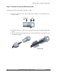
Step 9: Connect the PV Modules
WARNING: Electrical shock hazard. The DC conductors of this photovoltaic system are
ungrounded and may be energized.
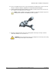
A. Connect the DC leads of each PV module to the DC input connectors of the corresponding
microinverter.
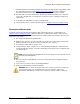
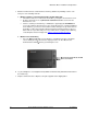
B. Check the LED on the connector side of the microinverter. The LED flashes six times when
DC power is applied.
C. Mount the PV modules above the microinverters.
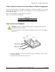
Status LED
DC Connector
AC Connector