
Installation Manual


IQ 6/IQ 6+ Micro Installation and Operation
© 2017 Enphase Energy Inc. All rights reserved. 141-00034-01
49
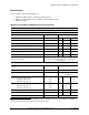
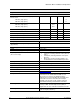
IQ6PLUS-72-2-US and IQ6PLUS-72-5-US Microinverter Specifications
IQ6PLUS-72-2-US Microinverter and IQ6PLUS-72-5-US Microinverter Parameters
Topic
Unit
Min
Typical
Max
DC Parameters
Commonly used module pairings
W
235 W - 400+ W
Peak Power Tracking Voltage
V
27
36
45
Operating range
V
16
62
Maximum DC input voltage
V
62
Minimum / Maximum start voltage
V
22
62
Maximum DC input short circuit current (module Isc)
A
15
Overvoltage class DC port
II
DC Port backfeed under single fault
A
0
PV array configuration
1 x 1 ungrounded array; No additional DC side protection
required; AC side protection requires max 20 A per
branch circuit
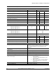
AC Parameters
Maximum Continuous AC output Power (-40 to
+65C)
VA
280
Peak output power
VA
290
Power factor (adjustable)
0.7 leading
0.7 lagging
Nominal AC output voltage range
240 VAC (single phase)
208 VAC (single phase)
Vrms
Vrms
211
183
240
264
229
Nominal output current
240 VAC (single phase)
208 VAC (single phase)
Arms
Arms
1.17
1.35
Nominal frequency
Hz
60
Extended frequency range
Hz
47
68
Maximum AC output over current protection device
A
20
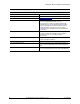
Maximum AC output fault current & duration
mA rms for 6
cycles
850
High AC Voltage trip limit accuracy
%
1.0
Low AC Voltage trip limit accuracy
%
1.0
Frequency trip limit accuracy
%
±0.1
Trip time accuracy
milliseconds
±33
Overvoltage class AC port
III
AC port backfeed under single fault
A
0
Power factor at rated power
1.0