
Guide


QUICK INSTALL GUIDE
Installing Enphase IQ 6 and IQ 6+ Microinverters
To install the Enphase IQ 6 and IQ 6+ Microinverters, read and follow all warnings and instructions in this guide and in the Enphase IQ 6 and IQ 6+ Microin-
verter Installation and Operation Manual at: enphase.com/support. Safety warnings are listed on the back of this guide.
The Enphase Microinverter models listed in this guide do not require grounding electrode conductors (GEC) or equipment grounding conductors (EGC). The
microinverter has a Class II double-insulated rating, which includes ground fault protection (GFP). To support GFP, use only PV modules equipped with DC
cables labeled PV Wire or PV Cable.
IMPORTANT: Enphase IQ Envoy and IQ 6 and IQ 6+ Micros do not communicate with, and should not be used with, previous generation Enphase Microin-
verters and Envoys. The Q Aggregator and other Q accessories work only with Enphase IQ 6 and/or IQ 6+ Microinverters.
D ) Check that you have these other items:
•
Enphase Q Aggregators or AC junction box
•
Number 2 and 3 Phillips screwdrivers
•
A 27 mm open-end wrench or channel lock pliers for terminator
•
Torque wrench, sockets, wrenches for mounting hardware
E ) Protect your system with lightning and/or surge suppression devices. It
is also important to have insurance that protects against lightning and
electrical surges.
F ) Plan your AC branch circuits to meet the following limits for maximum
number of microinverters per branch when protected with a 20-amp
over-current protection device (OCPD).
Max. IQ 6 Micros per 240V
branch circuit (single phase)
Max. IQ 6+ Micros per 240V
branch circuit (single phase)
16 13
Max. IQ 6 Micros per 208V
branch circuit(single phase)
Max. IQ 6+ Micros per 208V
branch circuit(single phase)
14 11
G ) Size the AC wire gauge to account for voltage rise. Select the correct
wire size based on the distance from the beginning of the Enphase Q
Cable to the breaker in the load center. Design for a voltage rise total of
less than 2% for the sections from the Enphase Q Cable to the breaker
in the load center. Refer to the Voltage Rise Technical Brief at
enphase.com/support for more information.
Best practice: Center-feed the branch circuit to minimize voltage rise in
a fully-populated branch.
PREPARATION
A ) Download the Enphase Installer Toolkit mobile app and
open it to log in to your Enlighten account. With this app,
you can scan microinverter serial numbers and connect
to the Enphase IQ Envoy to track system installation
progress. To download, go to enphase.com/toolkit or
scan the QR code at right.
B ) Refer to the following table and check PV module electrical compati-
bility at: enphase.com/en-us/support/module-compatibility.
Microinverter model DC Connector type PV module cell count
IQ6-60-2-US MC-4 locking Pair only with 60-cell
modules.
IQ6-60-5-US Amphenol UTX
IQ6PLUS-72-2-US MC-4 locking Pair with 60- or 72-cell
modules.
IQ6PLUS-72-5-US Amphenol UTX
To ensure mechanical compatibility, order the correct DC connector
type (MC-4 locking or Amphenol UTX) for both microinverter and PV
module from your distributor.
C ) In addition to the Enphase Microinverters, PV modules and racking,
you will need these Enphase items:
•
Enphase IQ Envoy (model ENV-IQ-AM1-240) communications
gateway: required to monitor solar production
•
Tie wraps or cable clips (Q-CLIP-100)
•
Enphase Sealing Caps (Q-SEAL-10): for any unused connectors on
the Enphase Q Cable
•
Enphase Terminator (Q-TERM-10): one needed at the end of each AC
cable segment
•
Enphase Disconnect Tool (Q-DISC-10)
•
Enphase Q Cable:
Cable model Connector
spacing
PV module
orientation
Connector count
per box
Q-12-10-240 1.3m Portrait 240
Q-12-17-240 2.0m Landscape (60-cell) 240
Q-12-20-200 2.3m Landscape (72-cell) 200
Allows for 30 cm of cable slack.
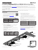
AC connector
Enphase
IQ 6 Micro or IQ 6+ Micro
DC connector
Enphase Q Aggregator or AC
junction box
terminator
Enphase
Q Cable
Tie wraps or
cable clips
© 2017 Enphase Energy, Inc. All rights reserved.
Enphase
disconnect
tool