INSTALLATION AND OPERATION MANUAL Enphase IQ 7, IQ 7+, IQ 7X, and IQ 7A Micros December 2019 141-00043-03
IQ 7 / IQ 7+ / IQ 7X / IQ 7A Micro Installation and Operation Corporate Headquarters Contact Information Enphase Energy Inc. 1420 N. McDowell Blvd. Petaluma, CA 94954 USA enphase.com/en-us/support/contact FCC Compliance This equipment has been tested and found to comply with the limits for a Class B digital device, pursuant to part 15 of the FCC Rules. These limits are designed to provide reasonable protection against harmful interference in a residential installation.
IQ 7 / IQ 7+ / IQ 7X / IQ 7A Micro Installation and Operation Table of Contents Important Safety Information .......................................................................................................................................... 5 Read this First .................................................................................................................................................. 5 Product Labels .................................................................................
IQ 7 / IQ 7+ / IQ 7X / IQ 7A Micro Installation and Operation Connector Spacing Options ........................................................................................................................... 27 Cabling Options .............................................................................................................................................. 27 Enphase Q Cable Accessories...........................................................................................................
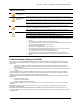
IQ 7 / IQ 7+ / IQ 7X / IQ 7A Micro Installation and Operation Important Safety Information Read this First This manual contains important instructions for use during installation and maintenance of the IQ 7™ Series Microinverters IMPORTANT: Enphase IQ Series Microinverters require the Q Cable and are not compatible with previous Enphase cabling. An IQ Envoy is required to monitor performance of the IQ Microinverters. The Q Accessories work only with Enphase IQ Series Microinverters.
IQ 7 / IQ 7+ / IQ 7X / IQ 7A Micro Installation and Operation DANGER: Risk of electric shock. Do not use Enphase equipment in a manner not specified by the manufacturer. Doing so may cause death or injury to persons, or damage to equipment. Be aware that installation of this equipment includes risk of electric shock. The DC conductors of this photovoltaic system are ungrounded and may be energized. Always de-energize the AC branch circuit before servicing.
IQ 7 / IQ 7+ / IQ 7X / IQ 7A Micro Installation and Operation Enphase Q Cable Safety DANGER: Risk of electric shock. WARNING: Risk of electric shock. Risk of fire. Do not install the Enphase Q Cable terminator while power is connected. When stripping the sheath from the Q Cable, make sure the conductors are not damaged. If the exposed wires are damaged, the system may not function properly. Do not leave AC connectors on the Q Cable uncovered for an extended period.
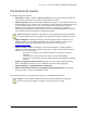
IQ 7 / IQ 7+ / IQ 7X / IQ 7A Micro Installation and Operation The Enphase IQ System The Enphase IQ System includes: • Enphase IQ 7™v, IQ 7+™, IQ 7A™ and IQ 7X™ Micros The smart grid ready IQ Series Micros convert the DC output of the PV module into grid-compliant AC power. • Enphase IQ Envoy™ (ENV-IQ-AM1-240) The Enphase IQ Envoy is a communication device that provides network access to the PV array.
IQ 7 / IQ 7+ / IQ 7X / IQ 7A Micro Installation and Operation How the Enphase IQ Series Micros Work The Enphase Microinverter maximizes energy production by using a sophisticated Maximum Power Point Tracking (MPPT) algorithm. Each Enphase Microinverter individually connects to one PV module in your array.
IQ 7 / IQ 7+ / IQ 7X / IQ 7A Micro Installation and Operation Planning for Microinverter Installation The Enphase IQ 7 Micro is compatible with 60-cell PV modules, and the IQ 7+ Micro and IQ 7A Micro support PV modules with 60 or 72 Cells. The IQ 7X requires a 96-cell PV module. All of them install quickly and easily.
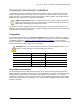
IQ 7 / IQ 7+ / IQ 7X / IQ 7A Micro Installation and Operation Branch Circuit Capacity Plan your AC branch circuits to meet the following limits for maximum number of microinverters per branch when protected with a 20 amp (maximum) over current protection device (OCPD).
IQ 7 / IQ 7+ / IQ 7X / IQ 7A Micro Installation and Operation Lightning and Surge Suppression Enphase Microinverters have integral surge protection, greater than most traditional inverters. However, if the surge has sufficient energy, the protection built into the microinverter can be exceeded, and the equipment can be damaged. For this reason, Enphase recommends that you protect your system with a lightning and/or surge suppression device.
IQ 7 / IQ 7+ / IQ 7X / IQ 7A Micro Installation and Operation Enphase Microinverter Installation Installing the Enphase IQ Series Micros involves several key steps. Each step listed here is detailed in the following pages.
IQ 7 / IQ 7+ / IQ 7X / IQ 7A Micro Installation and Operation Step 1: Position the Enphase Q Cable A. Plan each cable segment to allow drop connectors on the Enphase Q Cable to align with each PV module. Allow extra length for slack, cable turns, and any obstructions. B. Mark the approximate centers of each PV module on the PV racking. C. Lay out the cabling along the installed racking for the AC branch circuit. D. Cut each segment of cable to meet your planned needs.
IQ 7 / IQ 7+ / IQ 7X / IQ 7A Micro Installation and Operation Step 3: Mount the Microinverters A. Mount the microinverter bracket side up (as shown) and under the PV module, away from rain and sun. Allow a minimum of 1.9 cm (3/4”) between the roof and the microinverter. Also allow 1.3 cm (1/2”) between the back of the PV module and the top of the microinverter. WARNING: Install the microinverter under the PV module to avoid direct exposure to rain, UV and other harmful weather events.
IQ 7 / IQ 7+ / IQ 7X / IQ 7A Micro Installation and Operation Step 4: Create an Installation Map The Enphase Installation Map is a diagram of the physical location of each microinverter in your PV installation. Copy or use the blank map on page 39 to record microinverter placement for the system or provide your own layout if you require a larger or more intricate installation map. Each Enphase Microinverter, Envoy, and Battery have a removable serial number label.
IQ 7 / IQ 7+ / IQ 7X / IQ 7A Micro Installation and Operation Step 5: Manage the Cabling A. Use cable clips or tie wraps to attach the cable to the racking. Leave no more than 1.8 m (six feet) between cable clips or tie wraps. Cable clip B. Dress any excess cabling in loops so that it does not contact the roof. Do not form loops smaller than 12 cm (4¾ “) in diameter. WARNING: Tripping Hazard. Loose cables can become a tripping hazard. Dress the Enphase Q Cable to minimize this potential.
IQ 7 / IQ 7+ / IQ 7X / IQ 7A Micro Installation and Operation Step 7: Terminate the Unused End of the Cable Terminate the unused end of the Enphase Q Cable as follows. A. Remove 13 mm (½ inch) of the cable sheath from the conductors. Use the terminator loop to measure 13 mm. 13mm Terminator Body B. Slide the hex nut onto the cable. There is a grommet inside of the hex nut that should remain in place. C.
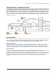
IQ 7 / IQ 7+ / IQ 7X / IQ 7A Micro Installation and Operation Step 8: Complete Installation of the Enphase Q Aggregator or Junction Box A. Connect the Enphase Q Cable into the Enphase Q Aggregator or junction box. B. Use the ground lug on the Q Aggregator for module, rack, and balance of system grounding, if needed. C. Refer to the wiring diagrams on page 41 for more information. Wire colors are listed in the following table.
IQ 7 / IQ 7+ / IQ 7X / IQ 7A Micro Installation and Operation Step 10: Energize the System A. Turn ON the AC disconnect or circuit breaker for the branch circuit. B. Turn ON the main utility-grid AC circuit breaker. Your system starts producing power after a five-minute wait time. C. Check the LED on the connector side of the microinverter: LED color Indicates Flashing green Normal operation. AC grid function is normal there is communication with the IQ Envoy.
IQ 7 / IQ 7+ / IQ 7X / IQ 7A Micro Installation and Operation Troubleshooting Follow all the safety measures described throughout this manual. Qualified personnel can use the following troubleshooting steps if the PV system does not operate correctly. WARNING: Risk of electric shock. Do not attempt to repair the Enphase Microinverter; it contains no user-serviceable parts.
IQ 7 / IQ 7+ / IQ 7X / IQ 7A Micro Installation and Operation Method 1: Clear this Error Using Enlighten • Log in to Enlighten and access the system. • Click the Events tab. The next screen shows a current “DC Resistance Low - Power Off” condition for the system. • Click DC Resistance Low - Power Off. • Where “n” is the number of affected devices, click n devices (show details). • Click the serial number of the affected microinverter. • Click Reset DC Resistance Low - Power Off Sensor.
IQ 7 / IQ 7+ / IQ 7X / IQ 7A Micro Installation and Operation Troubleshoot an Inoperable Microinverter To troubleshoot an inoperable microinverter, follow the steps in the order shown. WARNING: Risk of electric shock. Always de-energize the AC branch circuit before servicing. Never disconnect the DC connectors under load. WARNING: The Enphase Microinverters are powered by DC power from the PV modules.
IQ 7 / IQ 7+ / IQ 7X / IQ 7A Micro Installation and Operation indicates that the PV module isn’t functioning correctly. If it stays in place, the problem is with the original microinverter. Contact Enphase Customer Support for help in reading the microinverter data and for help in obtaining a replacement microinverter, if needed. M. Check the DC connections between the microinverter and the PV module. The connection may need to be tightened or reseated.
IQ 7 / IQ 7+ / IQ 7X / IQ 7A Micro Installation and Operation Install a Replacement Microinverter A. When the replacement microinverter is available, verify that the AC branch circuit breaker is de-energized. B. Mount the microinverter bracket side up and under the PV module, away from rain and sun. Allow a minimum of 1.9cm (0.75”) between the roof and the microinverter. Also allow 1.3cm (0.50”) between the back of the PV module and the top of the microinverter WARNING: Risk of equipment damage.
IQ 7 / IQ 7+ / IQ 7X / IQ 7A Micro Installation and Operation J. Add the new microinverter serial number to the Envoy database by initiating a device scan using one of the following methods: a. Method 1: Initiate a scan using the Installer Toolkit mobile app • In Installer Toolkit, once connected to the IQ Envoy, navigate to the Overview screen. • From the Overview screen, tap Detected > Start Device Scan to start a new 30minute device scan.
IQ 7 / IQ 7+ / IQ 7X / IQ 7A Micro Installation and Operation Ordering Replacement Parts Replacement adaptors for Microinverters with MC-4 DC connectors include: • Q-DCC-2: Cable Assembly, DC adaptor to MC-4 • Q-DCC-5: Cable Assembly, DC adaptor to Amphenol UTX These parts are available from your Enphase distributor. Enphase Q Cable Planning and Ordering The Enphase Q Cable is a continuous length of 12 AWG, double insulated, outdoor-rated cable with integrated connectors for microinverters.
IQ 7 / IQ 7+ / IQ 7X / IQ 7A Micro Installation and Operation Enphase Q Cable Accessories The Enphase Q Cable is available with several accessory options for ease of installation, including: 28 • Field wireable connectors (male): (Q-CONN-10M) Make connections from any Field Wireable female connector • Field wireable connectors (female): (Q-CONN-10F) Make connections from any Q Cable open connector or Field Wireable male connector • Enphase Q Aggregator: (Q-BA-3-1P-60) Aggregates up to three fully po
IQ 7 / IQ 7+ / IQ 7X / IQ 7A Micro Installation and Operation Technical Data Technical Considerations Be sure to apply the following when installing the Enphase IQ 7 Series Micro System: WARNING: Risk of equipment damage. You must match the DC operating voltage range of the PV module with the allowable input voltage range of the Enphase Microinverter. WARNING: Risk of equipment damage.
IQ 7 / IQ 7+ / IQ 7X / IQ 7A Micro Installation and Operation Specifications See specifications in the following tables for: • Enphase IQ7-60-2-US Microinverters • Enphase IQ7PLUS-72-2-US Microinverters • Enphase IQ7X-96-2-US Microinverters • Enphase IQ7A-72-2-US Microinverters • Enphase Q Cable IQ7-60-2-US Microinverter Specifications Enphase IQ7-60-2-US Microinverter Parameters Topic Unit Min Typical Max DC Parameters 235 W – 350+ W Commonly used module pairings1 Peak power tracking voltage V 27
IQ 7 / IQ 7+ / IQ 7X / IQ 7A Micro Installation and Operation Enphase IQ7-60-2-US Microinverter Parameters Topic Unit Min High AC voltage trip limit accuracy mVrms Low AC voltage trip limit accuracy mVrms 179 % ±0.1 Frequency trip limit accuracy Trip time accuracy Typical Max 280 milliseconds ±0.1% or 2 cycles Overvoltage class AC port III AC port backfeed under single fault A 0 Power factor setting 1.
IQ 7 / IQ 7+ / IQ 7X / IQ 7A Micro Installation and Operation Enphase IQ7-60-2-US Microinverter Parameters Topic Unit Min Typical Max Standard warranty term enphase.com/warranty Compliance CA Rule 21 (UL 1741-SA) UL 62109-1, UL1741/IEEE1547, FCC Part 15 Class B, ICES-0003 Class B, CAN/CSA-C22.2 NO. 107.1-01 This product is UL Listed as PV Rapid Shut Down Equipment and conforms with NEC-2014 and NEC-2017 section 690.12 and C22.
IQ 7 / IQ 7+ / IQ 7X / IQ 7A Micro Installation and Operation IQ7PLUS-72-2-US Microinverter Specifications IQ7PLUS-72-2-US Microinverter Parameters Topic Unit Min Typical Max DC Parameters Commonly used module pairings4 W 235 W - 440+ W Peak power tracking voltage V 27 Operating range V 16 Maximum DC input voltage V Minimum / maximum start voltage V Maximum DC input short circuit current (module Isc) A 36 45 60 60 22 60 15 Overvoltage class DC port II DC Port backfeed under single
IQ 7 / IQ 7+ / IQ 7X / IQ 7A Micro Installation and Operation IQ7PLUS-72-2-US Microinverter Parameters Topic Unit Min Typical Max Miscellaneous Parameters Maximum6 microinverters per 20A (max) AC branch circuit 240 VAC (single phase) 208 VAC (single phase) 13 11 CEC weighted efficiency 240 VAC (single phase) 208 VAC (single phase) Static MPPT efficiency (weighted, ref EN 50530) % Total harmonic distortion % % C Ambient temperature range Night tare loss 97.0 96.5 99.
IQ 7 / IQ 7+ / IQ 7X / IQ 7A Micro Installation and Operation IQ7X-96-2-US Microinverter Specifications IQ7X-96-2-US Microinverter Parameters Topic Unit Min Typical Max DC Parameters Commonly used module pairings7 W 320 W - 460+ W Peak power tracking voltage V 53 64 Operating range V 25 79.5 Maximum DC input voltage V Minimum / maximum start voltage V Maximum DC input short circuit current (module Isc) A 79.5 33 79.
IQ 7 / IQ 7+ / IQ 7X / IQ 7A Micro Installation and Operation IQ7X-96-2-US Microinverter Parameters Topic Unit Min Typical Max Miscellaneous Parameters Maximum9 microinverters per 20A (max) AC branch circuit 240 VAC (single phase) 208 VAC (single phase) 12 10 CEC weighted efficiency 240 VAC (single phase) 208 VAC (single phase) % Static MPPT efficiency (weighted, ref EN 50530) % Total harmonic distortion % Ambient temperature range C 97.5 97.0 Night tare loss 99.
IQ 7 / IQ 7+ / IQ 7X / IQ 7A Micro Installation and Operation IQ7A-72-2-US Microinverter Specifications IQ7A-72-2-US Microinverter Parameters Topic Unit Min Typical Max DC Parameters Commonly used module pairings10 W 295 W - 460+ W Peak power tracking voltage V 38 43 Operating range V 18 58 Maximum DC input voltage V Minimum / maximum start voltage V Maximum DC input short circuit current (module Isc) A 58 30 58 15 Overvoltage class DC port II DC Port backfeed under single fault
IQ 7 / IQ 7+ / IQ 7X / IQ 7A Micro Installation and Operation IQ7A-72-2-US Microinverter Parameters Topic Unit Min Typical Max Miscellaneous Parameters Maximum12 microinverters per 20A (max) AC branch circuit 240 VAC (single phase) 208 VAC (single phase) 11 11 CEC weighted efficiency 240 VAC (single phase) 208 VAC (single phase) Static MPPT efficiency (weighted, ref EN 50530) % Total harmonic distortion % % C Ambient temperature range Night tare loss 97.0 96.5 99.
IQ 7 / IQ 7+ / IQ 7X / IQ 7A Micro Installation and Operation Q Cable Specifications Specification Value Voltage rating 600V Voltage withstand test (kV/1min) AC 3.0 Max DC conductor resistance (20ºC) (Ω/km) 5.
IQ 7 / IQ 7+ / IQ 7X / IQ 7A Micro Installation and Operation Enphase Installation Map 40 © 2019 Enphase Energy Inc. All rights reserved.
© 2019 Enphase Energy Inc. All rights reserved. A B C D 8 ONE 2-POLE 20 AMP CIRCUIT BREAKER PER BRANCH CIRCUIT TO METER OR AC DISTRIBUTION PANEL 8 GROUND 7 AC DISTRIBUTION PANEL OR SUBPANEL NEUTRAL METER 7 Q CABLE BLACK - L1 RED - L2 4 NOTE: Ground PV modules according to local requirements. 5 3 TERMINATOR CAP INSTALLED ON END OF CABLE 6 5 4 or 12 IQ 7X MICROS PER 240 AC BRANCH CIRCUIT 1 3 2 © 2019 Enphase Energy Inc.