
Install Manual
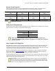
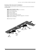
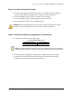
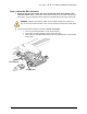
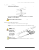
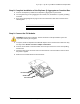
Table Of Contents
- Important Safety Information
- The Enphase IQ System
- Planning for Microinverter Installation
- Parts and Tools Required
- Enphase Microinverter Installation
- Step 1: Position the Enphase Q Cable
- Step 2: Position the Enphase Q Aggregator or Junction Box
- Step 3: Mount the Microinverters
- Step 4: Create an Installation Map
- Step 5: Manage the Cabling
- Step 6: Connect the Microinverters
- Step 7: Terminate the Unused End of the Cable
- Step 8: Complete Installation of the Enphase Q Aggregator or Junction Box
- Step 9: Connect the PV Modules
- Step 10: Energize the System
- Set Up and Activate Monitoring
- Troubleshooting
- Technical Data

IQ 7 / IQ 7+ / IQ 7X / IQ 7A Micro Installation and Operation
© 2019 Enphase Energy Inc. All rights reserved. 141-00043-03
17
Step 5: Manage the Cabling
A. Use cable clips or tie wraps to attach the cable to the racking. Leave no more than 1.8 m (six
feet) between cable clips or tie wraps.
Cable clip
B. Dress any excess cabling in loops so that it does not contact the roof. Do not form loops
smaller than 12 cm (4¾ “) in diameter.
WARNING: Tripping Hazard. Loose cables can become a tripping hazard. Dress the
Enphase Q Cable to minimize this potential.
Step 6: Connect the Microinverters
A. Connect the microinverter. Listen for a click as the connectors engage.
B. Cover any unused connector with Enphase Sealing Caps. Listen for a click as the connectors
engage.
WARNING: Risk of
electric shock. Risk of
fire. Install sealing caps
on all unused AC
connectors as these
connectors become
live when the system is
energized. Sealing
caps are required for
protection against
moisture ingress.
NOTE: If you need to
remove a sealing cap, you must use the Enphase Disconnect Tool. See “Disconnect a
Microinverter” on page 24.