
Q7 / IQ7+ / IQ7A / IQ7X Microinverter installation and operation manual
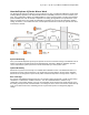
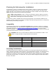
Table Of Contents
- Important Safety Information
- The Enphase IQ System
- Planning for Microinverter Installation
- Parts and Tools Required
- Enphase Microinverter Installation
- Step 1: Position the Enphase Q Cable
- Step 2: Position the Enphase Q Aggregator or Junction Box
- Step 3: Mount the Microinverters
- Step 4: Create an Installation Map
- Step 5: Manage the Cabling
- Step 6: Connect the Microinverters
- Step 7: Terminate the Unused End of the Cable
- Step 8: Complete Installation of the Enphase Q Aggregator or Junction Box
- Step 9: Connect the PV Modules
- Step 10: Energize the System
- Set Up and Activate Monitoring
- Troubleshooting
- Technical Data

IQ 7 / IQ 7+ / IQ 7X / IQ 7A Micro Installation and Operation
© 2019 Enphase Energy Inc. All rights reserved. 141-00043-03
10
Planning for Microinverter Installation
The Enphase IQ 7 Micro is compatible with 60-cell PV modules, and the IQ 7+ Micro and IQ 7A Micro
support PV modules with 60 or 72 Cells. The IQ 7X requires a 96-cell PV module. All of them install
quickly and easily. The microinverter housing is designed for outdoor installation and complies with the
NEMA 250, type 6 environmental enclosure rating standard:
NEMA 6 rating definition: Indoor or outdoor use primarily to provide a degree of protection
against hose-directed water, the entry of water during occasional temporary submersion at a
limited depth, and damage from external ice formation
The Enphase Q Cable is available with connector spacing options to accommodate installation of PV
modules in portrait or landscape orientation. For Enphase Q Cable ordering information, see “Enphase Q
Cable Planning and Ordering” on page 27.
Compatibility
The Enphase IQ Series Micros are electrically compatible with PV modules as listed in the following
table. For specifications, see “Technical Data” on page 29 of this manual. You can refer to the Enphase
Compatibility Calculator at: enphase.com/en-us/support/module-compatibility to verify PV module
electrical compatibility. To ensure mechanical compatibility, be sure to order the correct connector type
for both microinverter and PV module from your distributor.
WARNING: Risk of fire. The PV module DC conductors must be labeled "PV Wire" or "PV
Cable” to comply with NEC for Ungrounded PV Power Systems.
Microinverter model
Connector type
PV module cell count
IQ7A-72-2-US
MC-4 locking type
Pair with 60 or 72-cell modules
IQ7-60-2-US
MC-4 locking type
Pair only with 60-cell modules
IQ7PLUS-72-2-US
MC-4 locking type
Pair with 60 or 72-cell modules
IQ7X-96-2-US
MC-4 locking type
Pair only with 96-cell modules
IQ7A-72-2-US
MC-4 locking type
Pair with 60 or 72-cell modules
Grounding Considerations
The Enphase Microinverter models listed in this guide do not require grounding electrode conductors
(GEC), equipment grounding conductors (EGC), or grounded conductor (neutral). Your Authority Having
Jurisdiction (AHJ) may require you to bond the mounting bracket to the racking. If so, use UL2703
hardware or star washers. The microinverter itself has a Class II double-insulated rating, which includes
ground fault protection (GFP). To support GFP, use only PV modules equipped with DC cables labeled
PV Wire or PV Cable.