INSTALLATION AND OPERATION MANUAL Enphase Microinverter Model M215™ (M215-60-230) 141-00021, Rev 01
M215 Installation and Operation Corporate Headquarters Contact Information Enphase Energy Inc. 1420 N. McDowell Blvd. Petaluma, CA 94954 Phone: +1 707-763-4784 http://www.enphase.com info@enphaseenergy.com United Kingdom Contact Information Enphase Energy UK Ltd. Fairbourne Drive, Atterbury Milton Keynes, MK10 9RG United Kingdom Phone: +44 (0) 1908 828928 http://www.enphase.com/uk info@enphaseenergy.com Other Information For warranty text refer to http://www.enphase.com/uk/warranty.
M215 Installation and Operation Table of Contents Important Safety Information..........................................................................................................................4 Read this First ..................................................................................................................................4 Safety Instructions ............................................................................................................................
M215 Installation and Operation Important Safety Information Read this First This manual contains important instructions for use during installation and maintenance of the Enphase M215™ Microinverter. To reduce the risk of electrical shock, and to ensure the safe installation and operation of the Enphase Microinverter, the following safety symbols appear throughout this document to indicate dangerous conditions and important safety instructions.
M215 Installation and Operation The Enphase Microinverter System The Enphase Microinverter System is the world’s most technologically advanced inverter system for use in gridconnected applications. This manual details the safe installation and operation of the Enphase Microinverter.
M215 Installation and Operation How the Microinverter Works The Enphase Microinverter maximises energy production from your photovoltaic (PV) array. Each Enphase Microinverter is individually connected to one PV module in your array. This configuration means that an individual Maximum Peak Power Point Tracker (MPPT) controls each PV module.
M215 Installation and Operation Enphase Microinverter Installation Follow the instructions in this section to install Enphase M215™ Microinverters. WARNING: Be aware that only qualified personnel should connect the Enphase Microinverter to the electricity network. WARNING: Be aware that installation of this equipment includes risk of electric shock. Normally earthed conductors may be unearthed and energised when an earth fault is indicated.
M215 Installation and Operation Parts and Tools Required In addition to the microinverters, PV modules, mounting rail, and associated hardware, you will need the following. Enphase Equipment • • Enphase Envoy™ Communications Gateway Engage Cable, as needed NOTE: Order the correct Engage Cable type. Use 5G2.5 Engage Cable at sites with threephase service, or use 3G2.5 Engage Cable at sites with single-phase service. Check the labelling on the drop connectors to verify the voltage type.
M215 Installation and Operation Installation Procedure Installing the Enphase Microinverter System involves several key steps. Each step listed below is detailed in the following pages.
M215 Installation and Operation Step 2 – Install the AC Branch Circuit Junction Box DANGER: Risk of Electrical Shock. Be aware that installation of this equipment includes risk of electric shock. Do not install the AC junction box without first removing AC power from the Enphase System. WARNING: Only use electrical system components approved for wet locations. WARNING: Do NOT exceed the maximum number of microinverters in an AC branch circuit as listed on page 7 of this manual.
M215 Installation and Operation Step 3 – Position the Enphase Engage Cable 2 The Engage Cable is a continuous length of 2.5 mm , outdoor rated cable with integrated connectors for microinverters. These connectors are preinstalled along the Engage Cable at intervals to accommodate PV module widths. The microinverters plug directly into the connectors, and the Engage Cable is terminated into the junction box that feeds electricity back to the system AC disconnect.
M215 Installation and Operation Step 4 – Attach the Microinverters to the Mounting Rail a. Mark the approximate centres of each PV module on the mounting rail. b. Evaluate the location of the microinverter with respect to the PV module DC junction box or any other obstructions. • Ensure that the microinverter does not interfere with the PV module frame or stiffening braces. • Ensure that the connector from the microinverter can easily reach the connector on the Engage Cable. c. Allow a minimum of 1.
M215 Installation and Operation Step 5 – Dress the Engage Cable a. Attach the Engage Cable to the mounting rail using clips or tie wraps. NOTE: There are two release-holes in the drop connector on the cable. These are not for mounting but are used to disconnect the connector. Keep these release holes clear and accessible. release holes b. Dress any excess in loops so that the Engage Cable does not contact the roof. There are several ways to support the cable.
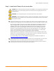
M215 Installation and Operation Step 6 – Connect the Microinverters a. Remove and discard the temporary shipping cap from the Engage Cable and connect the microinverter. There are two latching mechanisms within the connectors. Listen for two clicks as the connectors engage. Ensure that both latching mechanisms have engaged. b. Repeat for all microinverters in the AC branch circuit. c. Cover any unused connector with a sealing cap. Listen for two clicks as the connectors engage.
M215 Installation and Operation Step 7 – Terminate the Unused End of the Engage Cable Terminate the far end of the Engage Cable as follows. a. Remove 60mm (2.5 inches) of the cable sheath from the conductors. b. Slide the hex nut onto the Engage Cable. hex nut wire organiser cap c. Insert the Engage Cable all the way into the wire organiser (up to the stop). d. Bend the individual wires back into the recesses in the wire organiser so that they angle back toward the cable. e.
M215 Installation and Operation Step 8 – Connect the Engage Cable to AC Junction Box(es) a. Connect Engage Cable into the AC branch circuit junction box using an appropriate gland or strain relief fitting. The Engage Cable requires a strain relief connector with an opening of 1.3 cm (0.5 inches) in diameter. b. Connect the Engage Cable into additional AC junction boxes as needed to transition to conduit between smaller sub-arrays. Refer to the wiring diagrams located on page 28 for more information.
M215 Installation and Operation Step 9 – Complete the Installation Map The Enphase Installation Map is a diagrammatic representation of the physical location of each microinverter in your PV installation. The virtual array in Enlighten is created from the map you create. Use the blank map on page 27 to record microinverter placement for the system, or provide your own layout if a larger or more intricate installation map is required. Use the Enphase Installation Map a.
M215 Installation and Operation Step 11 – Build the Virtual Array When the system is energised and the Envoy detects all the installed microinverters, you can create the virtual array in Enlighten from the installation map you created. Once the virtual array is built, Enlighten displays a graphic representation of the PV system. It also shows detailed current and historical performance information. Please go to http://www.enphase.
M215 Installation and Operation Commissioning and Operation WARNING: Be aware that only qualified personnel must connect the Enphase Microinverter to the electricity network. WARNING: Ensure that all AC and DC wiring is correct. Ensure that none of the AC and DC wires are pinched or damaged. Ensure that all AC junction boxes are properly closed. NOTE: Obtain proper approval for the installation from the authorities having jurisdiction.
M215 Installation and Operation Troubleshooting Adhere to all the safety measures described throughout this manual. Qualified personnel can use the following troubleshooting steps if the PV system does not operate correctly. WARNING: Do not attempt to repair the Enphase Microinverter; it contains no user-serviceable parts. If it fails, please contact Enphase customer service to obtain an RMA (return merchandise authorisation) number and start the replacement process.
M215 Installation and Operation Troubleshoot an Inoperable Microinverter To troubleshoot an inoperable microinverter, follow the steps in the order shown. WARNING: Be aware that only qualified personnel should troubleshoot the PV array or the Enphase Microinverter. WARNING: Never disconnect the DC wire connectors under load. Ensure that no current is flowing in the DC wires prior to disconnecting. WARNING: Always disconnect AC power before disconnecting the PV module wires from the Enphase Microinverter.
M215 Installation and Operation Disconnect a Microinverter from the PV Module To ensure the microinverter is not disconnected from the PV modules under load, adhere to the following disconnection steps in the order shown: 1. De-energize the AC branch circuit breaker. 2. Disconnect the microinverter from the Engage Cable as follows: The Enphase AC connectors are tool-removable only.
M215 Installation and Operation Install a Replacement Microinverter 1. Verify that the AC branch circuit breaker is de-energised. 2. With the silver side of the microinverter facing up and the black side facing down, attach the replacement microinverter to the mounting rail using hardware recommended by your mounting rail vendor. 3. Torque the microinverter fasteners to the values below.
M215 Installation and Operation Technical Data Technical Considerations The Enphase M215 Microinverters are electrically compatible with most 60-cell PV modules. Be sure to verify the voltage and current specifications of your PV module match those of the microinverter. For more information, refer to our list of compatible PV modules at http://www.enphase.com/support/downloads.
M215 Installation and Operation Technical Specifications Enphase M215 Microinverter Parameters Topic Unit Min Typical Max DC Parameters Recommended maximum input power W 260 MPPT voltage range V 22 Operating range V 16 Maximum DC input voltage V Minimum / Maximum start voltage V Maximum DC input short circuit current A 15 Maximum DC input current A 10.5 29 36 36 45 22 45 AC Parameters Maximum AC output Power (-40 to 65 °C) W Output power factor 215 0.
M215 Installation and Operation Enphase M215 Microinverter Parameters Topic Unit Min Typical Max Features and Compliance Dimensions, not including mounting bracket (approximate) 17.3 cm x 16.4 cm x 2.5 cm (6.8” x 6.45” x 1.0”) Weight 1.6 Kg (3.
M215 Installation and Operation Enphase Installation Map 27 Copyright © 2012 Enphase Energy 141-00021 Rev 01
M215 Installation and Operation Sample Wiring Diagram – M215, 230 Vac, Single-Phase 28 Copyright © 2012 Enphase Energy 141-00021 Rev 01
M215 Installation and Operation Sample Wiring Diagram – M215, Three-Phase 29 Copyright © 2012 Enphase Energy 141-00021 Rev 01
M215 Installation and Operation 30 Copyright © 2012 Enphase Energy 141-00021 Rev 01
Corporate Headquarters Enphase Energy Inc. 1420 N. McDowell Blvd. Petaluma, CA 94954 Phone: +1 707-763-4784 http://www.enphase.com info@enphaseenergy.com United Kingdom Enphase Energy UK Ltd. Fairbourne Drive, Atterbury Milton Keynes, MK10 9RG United Kingdom Phone: +44 (0) 1908 828928 http://www.enphase.com/uk info@enphaseenergy.