I NS TA L L A TI O N A N D O P E R A TI O N MA NU A L Enphase M215 Microinverter 141-00012, Rev 06
M215 Installation and Operation Contact Information Enphase Energy Inc. 1420 N. McDowell Blvd. Petaluma, CA 94954 http://www.enphase.com info@enphaseenergy.com support@enphaseenergy.com FCC Compliance This equipment has been tested and found to comply with the limits for a Class B digital device, pursuant to part 15 of the FCC Rules. These limits are designed to provide reasonable protection against harmful interference in a residential installation.
M215 Installation and Operation Table of Contents Important Safety Information ..........................................................................................................................................5 Read this First..................................................................................................................................................5 Product Labels ..................................................................................................................
M215 Installation and Operation Technical Data ............................................................................................................................................................. 35 Technical Considerations............................................................................................................................... 35 Specifications......................................................................................................................................
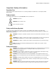
M215 Installation and Operation Important Safety Information Read this First This manual contains important instructions for use during installation and maintenance of the Enphase M215 Microinverter™. Product Labels The following symbols appear on the product label and are described here: WARNING: Hot surface. DANGER: Risk of electrical shock. Refer to product instructions.
M215 Installation and Operation WARNING: The body of the Enphase Microinverter is the heat sink. Under normal operating conditions, the temperature is 15°C above ambient, but under extreme conditions the microinverter can reach a temperature of 80°C. To reduce risk of burns, use caution when working with microinverters. WARNING: When pairing with an M215 (M215-60-2LL-S22-IG / S23-IG / S24-IG), the PV module DC conductors must be labeled “PV Wire” or “PV Cable”.
M215 Installation and Operation WARNING: Perform all electrical installations in accordance with all applicable local electrical codes and the National Electrical Code (NEC), ANSI/NFPA 70. NOTE: To ensure optimal reliability and to meet warranty requirements, the Enphase Microinverter must be installed according to the instructions in this manual. NOTE: The AC and DC connectors on the cabling are rated as a disconnect only when used with an Enphase Microinverter.
M215 Installation and Operation The Enphase Microinverter System ® The Enphase Microinverter System™ is the world’s most technologically advanced inverter system for use in utility-interactive applications. This manual details the safe installation and operation of the Enphase Microinverter. With the M215-60-2LL-S22-IG, S23-IG, or S24-IG, the DC circuit within the M215 is isolated and insulated from ground. Ground fault protection (GFP) is integrated into the microinverter.
M215 Installation and Operation How the Microinverter Works The Enphase Microinverter maximizes energy production from your photovoltaic (PV) array. Each Enphase Microinverter is individually connected to one PV module in your array. This unique configuration means that an individual Maximum Peak Power Point Tracker (MPPT) controls each PV module.
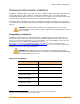
M215 Installation and Operation Planning for Microinverter Installation The M215 is compatible with most 60-cell PV modules (to 270W or higher) and installs quickly and easily. It works with either three-phase 208 VAC or single-phase 240 VAC services. The M215 ships with integrated DC and AC cables and connectors. The DC connectors attach to the PV module, while the AC connector attaches directly to the Engage Cable. No additional cabling is needed.
M215 Installation and Operation Grounding Considerations With the M215-60-2LL-S22-IG, S23-IG, or S24-IG, the DC circuit within the M215 is isolated and insulated from ground. Ground fault protection (GFP) is integrated into the microinverter. Because of this, the M215-60-2LL-S22-IG, S23-IG, and S24-IG do not require a GEC. As a result, they take less time to install than other microinverters, save money, and increase safety.
M215 Installation and Operation Parts and Tools Required In addition to the microinverters, PV modules, and racking, you will need the following. Enphase Equipment Enphase Envoy® Communications Gateway (optional, but strongly recommended) BEST PRACTICE: Connect the Envoy before the solar installation is complete. When powered up and connected for the first time, the Envoy may retrieve an automatic upgrade from Enphase.
M215 Installation and Operation Enphase Microinverter Installation Installing the Enphase Microinverter System involves several key steps. Each step listed here is detailed in the following pages. Follow the instructions in this section to install Enphase M215 Microinverters.
M215 Installation and Operation Step 1: Register the System Register the Envoy at the beginning of the PV installation. a. Use your previously issued username and password to log in to in Enlighten. If you haven’t registered, go to www.enphase.com and click Enlighten Login. b. At the installer dashboard, click Add a New System. If you have already registered the site, find the system under Installations in Progress. c. Under System, enter the system Name, Type and Installer Reference (optional). d.
M215 Installation and Operation Step 2: Connect the Envoy The Envoy operates between the Enphase Microinverters and the Enphase Enlighten® web-based monitoring and analysis software. The Envoy collects energy and performance data from the microinverters over on-site AC power lines. It then forwards that data to Enlighten, via the Internet, for statistical reporting. The Envoy is capable of monitoring up to 600 Enphase Microinverters. a.
M215 Installation and Operation Step 3: Install the AC Branch Circuit Junction Box DANGER: Risk of Electrical Shock. Be aware that installation of this equipment includes risk of electric shock. Do not install the AC junction box without first removing AC power from the Enphase System. WARNING: Only use electrical system components approved for wet locations. WARNING: Do NOT exceed the maximum number of microinverters in an AC branch circuit as listed on page 36 of this manual.
M215 Installation and Operation Step 4: Plan, Cut, and Position the Engage Cable 2 The Engage Cable is a continuous length of 12 AWG (2.5 mm ), outdoor-rated cable with integrated connectors for microinverters. These connectors are preinstalled along the Engage Cable at intervals to accommodate horizontal or vertical PV module widths. The microinverters plug directly into the connectors, and the Engage Cable is terminated into the junction box that feeds electricity back to the system AC disconnect.
M215 Installation and Operation Step 5: Attach the Microinverters to the PV Racking a. Mark the approximate centers of each PV module on the PV racking. b. Evaluate the location of the microinverter with respect to the PV module DC junction box or any other obstructions. c. Ensure that the microinverter does not interfere with the PV module frame or stiffening braces. d. Ensure that the connector from the microinverter can easily reach the connector on the Engage Cable. e. Allow a minimum of 1.9 cm (0.
M215 Installation and Operation Step 6: Ground the Microinverters (if required) This step is required only for M215-60-2LL-S22, S23, and S24. It is not required for M215-60-2LLS22-IG, S23-IG, or S24-IG. Each M215-60-2LL-S22, S23, and S24 comes with a grounding cleat (wire connector) that can accommodate a 6-8 AWG GEC (grounding electrode conductor). Check local requirements for allowable grounding conductor sizes.
M215 Installation and Operation Step 7: Dress the Engage Cable NOTE: Adhere to the following requirements: Do not expose the cable connections to directed, pressurized liquid (water jets, etc.). Do not expose the cable connections to continuous immersion. Do not expose the AC connector to continuous tension (e.g., tension due to pulling or bending the cable near the connection) Use only the connectors and cables provided. Do not allow contamination or debris in the connectors.
M215 Installation and Operation Step 8: Connect the Microinverters a. Remove and discard the temporary shipping caps from the Engage Cable and connect the microinverter. There are two latching mechanisms within the connectors. Listen for two clicks as the connectors engage. Ensure that both latching mechanisms have engaged. b. Repeat for all microinverters in the AC branch circuit. c. Cover any unused connector with a sealing cap. Listen for two clicks as the sealing cap engages.
M215 Installation and Operation Step 9: Terminate the Unused End of the Engage Cable WARNING: Risk of Electrical Shock. Do not install the terminator cap while power is connected. NOTE: Adhere to the following requirements: Use the terminator only once. If you open the terminator following installation, the latching mechanism is destroyed. Do not reuse the terminator. If the latching mechanism is defective, do not use the terminator.
M215 Installation and Operation Step 10: Connect the Engage Cable to AC Junction Box(es) a. Connect Engage Cable into the AC branch circuit junction box using an appropriate gland or strain relief fitting. The Engage Cable requires a strain relief connector with an opening of 1.3 cm (0.5 inches) in diameter. b. Connect the Engage Cable into additional AC junction boxes as needed to transition to conduit between smaller sub-arrays. Refer to the wiring diagrams on page 41 for more information.
M215 Installation and Operation Step 11: Complete the Installation Map The Enphase Installation Map is a diagrammatic representation of the physical location of each microinverter in your PV installation. You will create the virtual array in Enlighten from this map. Use the blank map on page 40 to record microinverter placement for the system, or provide your own layout if a larger or more intricate installation map is required.
M215 Installation and Operation Commissioning and Operation WARNING: Qualified personnel only may connect the Enphase Microinverter to the utility grid after receiving prior approval from the electrical utility company. WARNING: Ensure that all AC and DC wiring is correct. Ensure that none of the AC and DC wires are pinched or damaged. Ensure that all AC junction boxes are properly closed. Energize the System 1. Turn ON the AC disconnect or circuit breaker for each microinverter AC branch circuit. 2.
M215 Installation and Operation Build the Virtual Array When the system is energized and the Envoy detects at least one microinverter, create the virtual array in Enlighten from the installation map you created. You can scan and upload the paper copy of the Installation Map, or you can use the ArrayGun feature from the Enphase Installer Toolkit to easily build and configure a system. Refer to http://enphase.com/products/arraygun/ for more information. To scan and upload the map and build the array: 1.
M215 Installation and Operation Troubleshooting Adhere to all the safety measures described throughout this manual. Qualified personnel can use the following troubleshooting steps if the PV system does not operate correctly. WARNING: Do not attempt to repair the Enphase Microinverter; it contains no userserviceable parts. If the microinverter fails, contact Enphase customer service to obtain an RMA (return merchandise authorization) number and start the replacement process.
M215 Installation and Operation GFDI Fault For M215-60-2LL-S22, S23, or S24, a solid red status LED when DC power has been cycled indicates the microinverter has detected a ground fault (GFDI) error. The LED will remain red and the fault will continue to be reported by the Envoy until the error has been cleared. An Envoy is required to clear this condition. The condition usually clears with operator intervention unless conditions causing the event have not been remedied or if the failure is permanent.
M215 Installation and Operation 6. Verify that utility power is present at the microinverter by measuring line to line and line to neutral at the Engage Cable connector. 7. Visually check that the AC branch circuit connections (Engage Cable and AC connections) are properly seated. Reseat if necessary. Check also for damage, such as rodent damage. 8. Make sure that any upstream AC disconnects, as well as the dedicated circuit breakers for each AC branch circuit, are functioning properly and are closed. 9.
M215 Installation and Operation Disconnect a Microinverter If problems remain after following the troubleshooting steps listed previously, contact Enphase at support@enphaseenergy.com. If Enphase authorizes a replacement, follow the steps below. To ensure the microinverter is not disconnected from the PV modules under load, adhere to the following disconnection steps in the order shown: 1. De-energize the AC branch circuit breaker. 2.
M215 Installation and Operation Install a Replacement Microinverter If problems remain after troubleshooting, contact Enphase at support@enphaseenergy.com. If Enphase authorizes a replacement (RMA), replace the microinverter as follows: 1. When the replacement M215 is available, verify that the AC branch circuit breaker is deenergized. 2. Attach the replacement microinverter to the PV racking using hardware recommended by your PV racking vendor.
M215 Installation and Operation Engage Cable Planning and Ordering 2 The Engage Cable is a continuous length of 2.5 mm (12 AWG), outdoor-rated cable with integrated connectors for microinverters. These connectors are preinstalled along the Engage Cable at intervals to accommodate varying PV module widths. The microinverters plug directly into the cable connectors. The cabling is compatible with a variety of PV racking systems.
M215 Installation and Operation Voltage Type and Conductor Count Options The voltage types are either 240 VAC split phase or 208 VAC three phase. All cable connectors bear labels indicating the cable voltage designation. Typically used for residential applications, 240VAC includes four conductors. Three-phase 208 VAC cabling includes five conductors, and is used for most commercial installations.
M215 Installation and Operation You can sometimes avoid skipping Engage Cable connectors with the use of Engage Couplers. Use the Engage Coupler to connect two Engage Cables or to connect Engage Cable to field cable. There are many possible scenarios for each type of connection, but they generally fall into four categories: - Engage Cable to Engage Cable: 1. Make use of leftover lengths of Engage Cable 2. Transition between portrait and landscape Engage Cable - Engage Cable to Field Cable (#12 TC-ER): 3.
M215 Installation and Operation Technical Data Technical Considerations PV modules paired with the M215-60-2LL-S22-IG, S23-IG, or S24-IG must have conductors labeled "PV Wire" or "PV Cable” to be compliant with NEC 690.35(D) for Ungrounded PV Power Systems. Be sure to verify the voltage and current specifications of your PV module match those of the microinverter. WARNING: You must match the DC operating voltage range of the PV module with the allowable input voltage range of the Enphase Microinverter.
M215 Installation and Operation M215-60-2LL-S22-IG, S23-IG, or S24-IG Microinverter Parameters Topic Unit Min Typical Max AC Parameters Rated (continuous) AC output Power (-40 to +65C) W 215 Peak AC output power W 225 Output power factor Nominal AC output voltage range 240 VAC (split phase) 208 VAC (three phase) Vrms Vrms Maximum AC output current at nominal voltage 240 VAC (split phase) 208 VAC (three phase) Arms Arms 0.95 0.99 1 211 183 240 208 264 229 0.9 1.
M215 Installation and Operation M215-60-2LL-S22-IG, S23-IG, or S24-IG Microinverter Parameters Topic Unit Min Typical Max Features and Specifications Compatibility Pairs with most 60-cell PV modules (the PV module DC conductors must be labeled "PV Wire" or "PV Cable” to be compliant with NEC 690.35(D) for Ungrounded PV Power Systems) Dimensions not including mounting bracket (approximate) 163 mm x 173 mm x 2.5 mm (6.4” x 6.8” x 1.0”) Weight 3.4 Lbs (1.
M215 Installation and Operation M215-60-2LL-S22, S23 or S24 Microinverter Parameters Topic Unit Min Typical Max W 215 0.95 0.
M215 Installation and Operation M215-60-2LL-S22, S23 or S24 Microinverter Parameters Topic Unit Min Typical Max Features and Specifications Compatibility Pairs with most 60-cell PV modules Dimensions not including mounting bracket (approximate) 163 mm x 173 mm x 2.5 mm (6.4” x 6.8” x 1.0”) Weight 3.4 Lbs (1.6 Kg) Enclosure environmental rating NEMA 6 Torque specifications for fasteners (Do not over torque.
M215 Installation and Operation Enphase Installation Map 40 2014 Enphase Energy Inc. All rights reserved.
M215 Installation and Operation Sample Wiring Diagram: M215, 240 VAC 41 2014 Enphase Energy Inc. All rights reserved.
M215 Installation and Operation Sample Wiring Diagram: M215, 208 VAC 42 2014 Enphase Energy Inc. All rights reserved.