
Install Manual
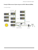
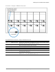
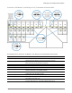
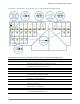
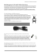
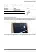
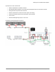
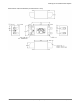
Table Of Contents
- Planning for an IQ Microinverter System
- IQ 6 and IQ 6+ Micros
- Q Cable and IQ Micro Accessories
- IQ System Design using the IQ Combiner
- IQ System Design with Q Aggregator
- Field Wireable Q Connectors and Raw Q Cable
- Splicing Q Cable and Raw Q Cable with Junction Boxes
- Example IQ Microinverter System Layouts and Bill of Materials (BOMs)
- Wire Management of AC and DC Cables Under Array
- AC Wire Management at the Junction Box or Q Aggregator
- Installing IQ Microinverters with Frame Mount Bracket
- Installing the Power Line Filter (Q-LCF-064-1)

Planning for an IQ Microinverter System
© 2017 Enphase Energy Inc. All rights reserved. July 28, 2017
21
Specifications of Q-LCF-064 Filter
• Shall be installed within a suitable enclosure.
• Wire Enphase IQ Envoy/Micros on the load side and utility/site loads on the line side of the filter.
• Wiring terminals accept #4 to #22 conductors
• 250Vac / 64A maximum continuous inverter output current rating
• Protect with maximum 80A overcurrent protection device (OCPD)
• -25°C to 65°C
• Recommended tightening torque of 2 to 2.8 Nm
Schematic of Q-LCF-064 Filter Installation