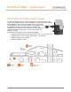
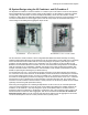
TECHNICAL BRIEF – North America Planning for an IQ Microinverter System The Enphase IQ Microinverter™ system is inexpensive to install and provides a wide range of new installation options to solar professionals. It is the ideal product for singlephase applications. New components available as part of this system provide additional options for reducing balance of system (BOS) costs and installation complexity.
Planning for an IQ Microinverter System IQ 6 and IQ 6+ Micros The IQ 6 and IQ 6+ Micros have a 97% CEC efficiency for single-phase applications and are available at peak output power ratings of 240 watts and 290 watts respectively. For a single-phase, 240V application, you can install a maximum of 16 IQ 6 Micros or 13 IQ 6+ Micros on a 20A branch circuit. See the IQ product data sheet for complete product specifications at enphase.com.
Planning for an IQ Microinverter System Q Cable and IQ Micro Accessories The IQ Microinverter System uses the new Q Cable with only two conductors, resulting in a lighter and more flexible product. This UL3003 listed DG (Distributed Generation) cabling system is purpose designed for the application, and uses the following new accessories, which are not compatible with earlier Enphase cabling systems.
Planning for an IQ Microinverter System Specifying Cabling and Accessories at the Array The Enphase IQ Microinverter system uses a new and improved cabling system. The Q Cable is DG type and contains only two #12 AWG line conductors. The Q Cable male connectors plug directly into the IQ Micros, whose double insulation rating requires no neutral or ground conductors. This lightweight cable drives down system costs while simplifying installation.
Planning for an IQ Microinverter System You must install supports (clips, etc.) for the Q Cable and raw Q Cable at six-foot intervals or less. Installation requirements for wet-rated cable allow Q Cable and raw Q Cable to be installed in conduits, cable trays, and other raceways. Q Cable is a UL3003 DG (Distributed Generation) listed cabling system. The DG cable standard UL3003 is based upon the construction specifications (wet rated) of TC-ER cable, which may be installed in raceway as per NEC 336.10(3).
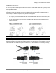
Planning for an IQ Microinverter System Field Wireable Q Connectors You can use the male or female Field Wireable Q Connectors to extend the Q Cable (with connectors) or the raw Q Cable (without connectors). Installers assemble the Field Wireable Q Connectors using a crimp tool and the provided terminals. Enphase recommends the Multi-Contact PV-CZM-18100, -19100, or -22100 crimp tools.
Planning for an IQ Microinverter System Sealing Caps You must seal each unused Q Cable connector with a watertight sealing cap (Q-SEAL). Male connector on Q Cable Female Sealing Cap (Q-SEAL) Seal each unused connector on the Q Aggregator with a male sealing cap. Also, during construction, you must use male sealing caps to temporarily seal any exposed IQ Micro connectors, that are not connected to the Q Cable, to protect against moisture or water damage at the exposed connector.
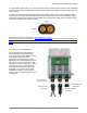
Planning for an IQ Microinverter System IQ System Design using the IQ Combiner The Enphase IQ CombinerTM combines up to three AC branch circuits of an IQ System, has an integrated IQ Envoy and is UL listed. Using an IQ Combiner makes the customer “storage ready,” as it also allows connection of Enphase IQ Battery circuits. The IQ Combiner design and installation is similar to the previous Enphase AC Combiner Box. The primary difference is that it includes a pre-installed IQ Envoy.
Planning for an IQ Microinverter System IQ System Design using the IQ Combiner+ and IQ Combiner 3 The Enphase IQ Combiner+TM and IQ Combiner 3TM combine up to four AC branch circuits of an IQ System, have integrated IQ Envoy and are UL listed. Using an IQ Combiner+ or IQ Combiner 3 makes the customer “storage ready,” as it also allows connection of Enphase IQ Battery circuits.
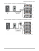
Planning for an IQ Microinverter System Conceptual Schematics of IQ Combiner 3 (or IQ Combiner+) Installation Conceptual Schematics of IQ Combiner 3 (or IQ Combiner+) with Q Aggregator Installation 10 © 2018 Enphase Energy Inc. All rights reserved.
Planning for an IQ Microinverter System IQ System Design with Q Aggregator The IQ Microinverter system introduces a new rooftop mounted, singlephase Q Aggregator (Q-BA-3-1P-60), which enables plug and play termination and combining up to three microinverter AC branch circuits at a single location. The Q Aggregator offers additional design options and can help to lower balance of system installation costs for many projects.
Planning for an IQ Microinverter System IQ Envoy Installation Options IQ Combiner with Factory-Installed IQ Envoy The IQ Envoy is factory-installed as part of the Enphase IQ Combiner, but in that case the Q Aggregator circuit cannot terminate in the IQ Combiner if the total of the Q Aggregator’s microinverter output circuits exceed 16A. The IQ Combiner with IQ Envoy contains three 20A branch circuit breakers and cannot support larger breakers.
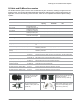
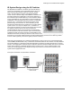
Planning for an IQ Microinverter System • One 2-pole, 20A circuit breaker for each microinverter branch circuit, suitable for backfeed operation • A NEMA type 3R, 4, or better enclosure with hinged or screw cover for housing the IQ Envoy • An IQ Envoy (ENV-IQ-AM1-240) • Miscellaneous conduits, fittings and conductors to make a code compliant installation Conceptual Schematic of an IQ Envoy and Solar Subpanel Installation Installing the IQ Envoy in an Outdoor Enclosure The IQ Envoy must be installed
Planning for an IQ Microinverter System • Consider placing the enclosure in a location that is accessible by service personnel without requiring indoor access. • The IQ Envoy ships with a production CT. This must be installed in the solar subpanel to meter the microinverter branch circuit conductors. • Metering CT requirements: o Use a protected route in conduit for the production CT wires from the solar subpanel to the IQ Envoy.
Planning for an IQ Microinverter System Integra H12104H*** Enclosures • Strong metal or poly backplate options, NEMA4, lockable • Approximate dimensions are 10"x12"x5" • Easily accommodates addition of a field wired receptacle, if needed • Manufacturer provides a wide variety of enclosure options, including mounting tabs, and vents Attabox AH12106 Enclosure with BP1210A back plate • Strong metal or poly backplate options, NEMA4, lockable • Approximate dimensions are 10"x12"x5" • Easily accommod
Planning for an IQ Microinverter System Field Wireable Q Connectors and Raw Q Cable The IQ Microinverter System makes complex installations simple. Field Wireable Q Connectors (Q-CONN-10F and Q-CONN-10M) and raw Q Cable (Q-12-RAW-300) allow a wide-range of installation options that are not available in DC systems or other microinverter systems.
Planning for an IQ Microinverter System Splicing Q Cable and Raw Q Cable with Junction Boxes For complex installations that include multiple arrays, it is possible to use raw Q Cable (Q-12-RAW-300) to service the arrays and branch circuits that do originate directly at the primary roof mounted junction box. In the case that Field Wireable Q Connectors are not readily available, a small junction box may be used to splice two sections of Q Cable together or may be used to splice Q Cable to raw Q Cable.
Planning for an IQ Microinverter System Example IQ Microinverter System Layouts and Bill of Materials (BOMs) Conceptual Image 18 © 2018 Enphase Energy Inc. All rights reserved.
Planning for an IQ Microinverter System Scenario 1: Simple 12 Module Scenario Bill of Materials for Scenario 1: Simple 12 Module Scenario QTY Part Number Description 12 IQ6PLUS-72-2-US 12 of 240 Q-12-10-240 0 of 10 Q-SEAL-10 Enphase IQ 6+ Microinverter, compatible with 60- and 72-cell PV modules, 290VA peak power, MC4 DC connectors, female AC connector Q Cable for 60/72 cell 1.0m portrait module pitch. Connector pitch is 1.3m.
Planning for an IQ Microinverter System Scenario 2: 24 Module, Two Strings of 12, Terminated at Junction Box Bill of Materials for Scenario 2: 24 Modules, Two Strings of 12 Terminated at Junction Box QTY Part Number Description 24 IQ6PLUS-72-2-US Enphase IQ 6+ Microinverter, compatible with 60- and 72-cell PV modules, 290VA peak power, MC4 DC connectors, female AC connector 26 of 240 Q-12-10-240 Q Cable for 60/72 cell 1.0m portrait module pitch. Connector pitch is 1.3m.
Planning for an IQ Microinverter System Scenario 3: 24 Module, Two Strings of 12, Terminated at Q Aggregator Bill of Materials for Scenario: 24 Modules, Two Strings of 12 Terminated at Q Aggregator QTY Part Number Description 24 IQ6PLUS-72-2-US 27 of 240 Q-12-10-240 x ft of 984 Q-12-RAW-300 Q Cable, 12 AWG, no connectors, 300m (984ft) length 2 of 10 Q-SEAL-10 Female sealing cap for unused Q Cable connectors. Pack of 10 3 of 10 Q-TERM-10 Q Terminator for Q Cable ends.
Planning for an IQ Microinverter System Wire Management of AC and DC Cables Under Array Since the Q Cable contains only two conductors, it is much smaller and lighter than the previous generation Engage Cable. For this reason, we use cable clips with a reduced wire retention area for the Q Cable. The outer dimensions of the Q Cable allow it to be supported by many of the existing PV cable clips and USE-2 cable clips that are frequently used for supporting the DC module leads today.
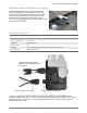
Planning for an IQ Microinverter System You must support the Q Cable and raw Q Cable at intervals not to exceed 6 feet and make sure that the cable does not touch the roof surface. Manufacturer Model Nine Fasteners DCS-1307 PV cable clip DCS-1306 USE-2 cable clip Burndy / Wiley Electronics ACME ACC-PV PV cable clip Heyco Products SunRunner PV cable clip Image Supporting the DC Module Leads Prepare the modules using clips on the DC module leads to prevent the leads from resting on the roof.
Planning for an IQ Microinverter System AC Wire Management at the Junction Box or Q Aggregator Wire management practices at the junction box are critical to the long-term reliability of any PV system. Installers often install the roof-mounted junction box on the side of a rail. If using the Q Aggregator, it must be installed underneath the modules. For Junction Box Applications Follow these recommendations to prevent moisture from accumulating in the junction box.
Planning for an IQ Microinverter System Installing IQ Microinverters with Frame Mount Bracket You can use the Enphase Frame Mount to attach the Enphase Microinverters directly to module frames. This may be the ideal solution for rail-less racking solutions, whether residential or commercial. When using the Enphase Frame Mount product, you can support the Q Cable to keep it off the roof by clipping it to the module frames using the same module edge wire clips that work with PV cable and USE-2 cable.
Planning for an IQ Microinverter System Specifications of Q-LCF-064-1P Filter • Shall be installed within a suitable enclosure. • Wire Enphase IQ Envoy/Micros on the load side and utility/site loads on the line side of the filter. • Wiring terminals accept #4 to #22 conductors • 250VAC / 64A maximum continuous inverter output current rating • Protect with maximum 80A overcurrent protection device (OCPD) • -25°C to 65°C • Recommended tightening torque of 2 to 2.