
Data Sheet
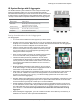
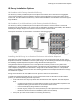
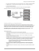
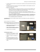
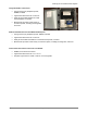
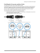


Table Of Contents
- Planning for an IQ Microinverter System
- IQ 6 and IQ 6+ Micros
- IQ 7 and IQ 7+ Micros
- IQ 7X Micros
- Q Cable and IQ Micro Accessories
- IQ System Design using the IQ Combiner
- IQ System Design using the IQ Combiner+ and IQ Combiner 3
- IQ System Design with Q Aggregator
- IQ Envoy Installation Options
- Field Wireable Q Connectors and Raw Q Cable
- Splicing Q Cable and Raw Q Cable with Junction Boxes
- Example IQ Microinverter System Layouts and Bill of Materials (BOMs)
- Wire Management of AC and DC Cables Under Array
- AC Wire Management at the Junction Box or Q Aggregator
- Installing IQ Microinverters with Frame Mount Bracket
- Installing the Power Line Filter (Q-LCF-064-1P)

Planning for an IQ Microinverter System
© 2018 Enphase Energy Inc. All rights reserved. December 13, 2018
16
Field Wireable Q Connectors and Raw Q Cable
The IQ Microinverter System makes complex installations simple.
Field Wireable Q Connectors (Q-CONN-10F and Q-CONN-10M) and raw Q Cable (Q-12-RAW-300) allow a
wide-range of installation options that are not available in DC systems or other microinverter systems. You
can run raw Q Cable through conduits, raceways, or chases between sub-arrays to help to minimize the
amount of conduit, conduit bending, wire-pulls, and wiring connections that are required on a project.
The raw Q Cable is available in 300m (984ft) cable rolls (Q-12-RAW-300).
You must terminate the raw Q Cable in one of the following manners:
• Into a junction box using a ½” service entrance (SE) strain reliefs, UF cable glands, or Heyco® -Tite
Liquid Tight Cordgrips for Enphase Q Cables
• With a Field Wireable Q Connector (male or female)
Female Field Wireable
Q Connector
Male Field Wireable
Q Connector