
Data Sheet
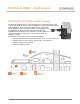
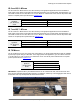
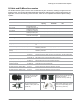
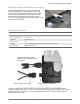
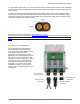
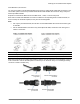
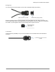
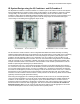
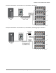
Table Of Contents
- Planning for an IQ Microinverter System
- IQ 6 and IQ 6+ Micros
- IQ 7 and IQ 7+ Micros
- IQ 7X Micros
- Q Cable and IQ Micro Accessories
- IQ System Design using the IQ Combiner
- IQ System Design using the IQ Combiner+ and IQ Combiner 3
- IQ System Design with Q Aggregator
- IQ Envoy Installation Options
- Field Wireable Q Connectors and Raw Q Cable
- Splicing Q Cable and Raw Q Cable with Junction Boxes
- Example IQ Microinverter System Layouts and Bill of Materials (BOMs)
- Wire Management of AC and DC Cables Under Array
- AC Wire Management at the Junction Box or Q Aggregator
- Installing IQ Microinverters with Frame Mount Bracket
- Installing the Power Line Filter (Q-LCF-064-1P)

Planning for an IQ Microinverter System
© 2018 Enphase Energy Inc. All rights reserved. December 13, 2018
4
Specifying Cabling and Accessories at the Array
The Enphase IQ Microinverter system uses a new and
improved cabling system. The Q Cable is DG type and
contains only two #12 AWG line conductors. The Q Cable
male connectors plug directly into the IQ Micros, whose
double insulation rating requires no neutral or ground
conductors. This lightweight cable drives down system costs
while simplifying installation.
Designing with Q Cable
Q CABLE SPECIFICATIONS
Voltage rating
600V (connector rating 250 V)
Cable temperature rating
90° C (194° F)
Certification
UL3003, DG cable
Flame test rating
FT4
Compliance
RoHS, OIL RES I, CE, UV resistant, combined UL for the United States
Conductor rating
THHN/THWN-2 dry/wet
Q Cable is a single-phase, two-line conductor cable with integrated AC connectors available in three
connector-spacing configurations for different PV module sizes and layouts. Also offered is a raw Q Cable
without integrated AC connectors for runs between separated arrays or to a junction box located some
distance away from an array.
IQ Micro part numbers offered
with either MC4 or Amphenol UTX
DC Adaptors
Male connector on Q Cable
Female connector on IQ Micro