
Install Manual
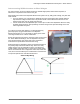
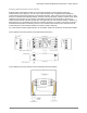
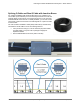
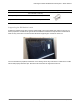
Table Of Contents
- IQ Micros on a Three Phase System
- IQ Commercial Envoy
- Q Cable and IQ Microinverter Accessories
- Commercial IQ System Design
- Three-phase, 208Y/120V System Design
- 208Y/120V Electrical Service Conceptual Schematic
- Ampacity Calculations for 208V Branch Circuits on Two-Pole Circuit Breakers
- Ampacity Calculations for Three-Phase Feeders to 208Y/120V Solar Subpanel
- Example 208Y/120V Electrical Schematic
- Example 208Y/120V Basic Building Block Single Line Diagram for IQ 7+ with optional field-assembled Micro panel, keeping within maximum 249 Micros per Envoy recommendation.
- Interconnecting IQ Microinverters to Other Voltages
- Three-phase, 208Y/120V System Design
- Multiple IQ Commercial Envoys on a Single Site — Filtering Communication Domains
- Splicing Q Cable and Raw Q Cable with Junction Boxes
- Wire Management of AC and DC Cables Under Array
- AC Wire Management at the Junction Box
- Installing IQ Microinverters with Frame Mount Bracket
- Appendix A: Lightning and Surge Suppression in Commercial Systems
- Appendix B: Phase Loss Protection

Planning a Commercial IQ Microinverter System – North America
© 2020 Enphase Energy Inc. All rights reserved. January 27, 2020
13
Interconnecting IQ Microinverters to Other Voltages
For interconnection to system voltages other than 120/208 single-phase, 208Y/120V three-phase, a
transformer is required to interconnect to the grid.
While transformers interconnect Enphase Microinverter Systems to any utility power voltage, they also offer
other benefits.
• For many projects, it is cost effective to distribute the power at the higher utility voltages and then
step down the voltage to 208Y/120V. This practice results in more transformers but can be cost
effective when wire runs are greater than 250 feet.
• Choose transformers with adjustable taps. Use the tap to make minor adjustments when the utility-
provided voltage is high or when optimizing conductor sizing versus expected voltage rise for the
value engineered PV system.
It is common to specify high-efficiency or ultra-high efficiency,
general purpose, dry-type transformers for an Enphase
Microinverter System. It is not necessary to specify power factor
correcting transformers or K-factor transformers.
Specify the transformer kVA size to meet the inverter output in kW
AC. Some additional deratings, such as adjustments for power
factor and temperature may apply. Refer to the transformer
manufacturer’s specifications for transformer sizing.
Most transformers for Enphase systems are specified as delta on
the primary/utility side and as 208/120 Wye. Even if the utility
voltage is Wye, such as a 480Y/277V service, it is still best to
provide a delta configuration with no neutral to the primary/utility
side of the transformer. This configuration works well, lowers wire
costs, and is recommended by the manufacturers of transformers
for improved performance and reduced harmonics.
Delta and Wye Wiring