
Install Manual
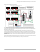
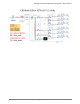
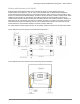

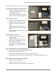
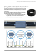
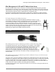
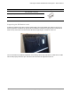
Table Of Contents
- IQ Micros on a Three Phase System
- IQ Commercial Envoy
- Q Cable and IQ Microinverter Accessories
- Commercial IQ System Design
- Three-phase, 208Y/120V System Design
- 208Y/120V Electrical Service Conceptual Schematic
- Ampacity Calculations for 208V Branch Circuits on Two-Pole Circuit Breakers
- Ampacity Calculations for Three-Phase Feeders to 208Y/120V Solar Subpanel
- Example 208Y/120V Electrical Schematic
- Example 208Y/120V Basic Building Block Single Line Diagram for IQ 7+ with optional field-assembled Micro panel, keeping within maximum 249 Micros per Envoy recommendation.
- Interconnecting IQ Microinverters to Other Voltages
- Three-phase, 208Y/120V System Design
- Multiple IQ Commercial Envoys on a Single Site — Filtering Communication Domains
- Splicing Q Cable and Raw Q Cable with Junction Boxes
- Wire Management of AC and DC Cables Under Array
- AC Wire Management at the Junction Box
- Installing IQ Microinverters with Frame Mount Bracket
- Appendix A: Lightning and Surge Suppression in Commercial Systems
- Appendix B: Phase Loss Protection

Planning a Commercial IQ Microinverter System – North America
© 2020 Enphase Energy Inc. All rights reserved. January 27, 2020
18
Splicing Q Cable and Raw Q Cable with Junction Boxes
For complex installations that include multiple arrays, it is possible to use
raw Q Cable (Q-12-RAW-300) to service the arrays and branch circuits that
originate directly at the primary roof mounted junction box. In the case that
Field Wireable Q Connectors are not readily available, you can use a small
junction box to splice two sections of Q Cable together or to splice Q Cable
to raw Q Cable.
The raw Q Cable is available in 300m (984ft) cable rolls (Q-12-RAW-300).
Terminate the raw Q Cable in one of the following manners:
• Into a junction box using a ½” service entrance (SE) strain reliefs,
UF cable glands, or Heyco® -Tite Liquid Tight Cordgrips for
Enphase Q Cables
• With a Field Wireable Q Connector (male or female)