
Install Manual
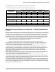
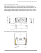
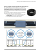
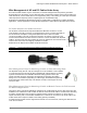
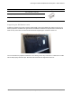
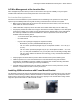
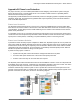
Table Of Contents
- IQ Micros on a Three Phase System
- IQ Commercial Envoy
- Q Cable and IQ Microinverter Accessories
- Commercial IQ System Design
- Three-phase, 208Y/120V System Design
- 208Y/120V Electrical Service Conceptual Schematic
- Ampacity Calculations for 208V Branch Circuits on Two-Pole Circuit Breakers
- Ampacity Calculations for Three-Phase Feeders to 208Y/120V Solar Subpanel
- Example 208Y/120V Electrical Schematic
- Example 208Y/120V Basic Building Block Single Line Diagram for IQ 7+ with optional field-assembled Micro panel, keeping within maximum 249 Micros per Envoy recommendation.
- Interconnecting IQ Microinverters to Other Voltages
- Three-phase, 208Y/120V System Design
- Multiple IQ Commercial Envoys on a Single Site — Filtering Communication Domains
- Splicing Q Cable and Raw Q Cable with Junction Boxes
- Wire Management of AC and DC Cables Under Array
- AC Wire Management at the Junction Box
- Installing IQ Microinverters with Frame Mount Bracket
- Appendix A: Lightning and Surge Suppression in Commercial Systems
- Appendix B: Phase Loss Protection

Planning a Commercial IQ Microinverter System – North America
© 2020 Enphase Energy Inc. All rights reserved. January 27, 2020
23
Appendix B: Phase Loss Protection
For project success, you must consider phase balance when designing commercial PV systems using IQ
Micros that interconnect to a three-phase service. You must also consider if there is a possibility that the
electrical service with may lose a phase.
This appendix provides details and recommends best practices for designing systems compatible with phase
imbalance, phase loss, and neutral sense guidelines that may be required by some AHJs and/or utilities to
meet recent IEEE requirements.
Phase Loss Scenarios
The Enphase IQ Series Microinverters connect to two of the three available phases of a three-phase 208V
WYE service. Since the Q Cable is a two-wire line to line cable and branch circuits are connected to two-pole
circuit breakers, system design should consider balancing out the number of microinverters across all three
phases in the panel board.
If a grid failure occurs only on one phase (ground fault or load rejection), then one third of the microinverters
connected to the other two phases may be unable to detect the failure. These microinverters may continue to
export power on those phases, contributing to a phase imbalance present on the local grid node.
Phase Loss Hardware Solution
In jurisdictions where the utility requires compliance to IEEE 1547, Enphase requires the use of a phase loss
relay system (NPR-3P-208-NA) described in this section. A phase loss relay system is not required for the IQ
microinverter to function but may be required by some AHJs and/or utilities to meet recent revisions to IEEE
1547and/or local code requirements. In such instances, it is mandatory that the Enphase product “NPR-3P-
208-NA” be specified to maintain UL listing of the IQ system.
A phase loss relay system consists of:
• A phase loss relay that monitors the three-line voltages and detects loss of phase
• A contactor that opens all three lines of the circuit to disrupt the power flow
• A UPS to ensure the relay can reconnect after loss of power.
The Enphase product will be built around the SEL-547 and an ABB 24V contactor. All of the components will
be available off the shelf. However, it will need to be assembled by Enphase to bear the UL mark. The device
only supports 208V Wye connection since a neutral is required to power the Envoy.
Install the combined relay-contactor system on the PV system side of the interconnection point and on the
grid side of the power line filter. For systems with no power line filter, install the relay-contactor system on the
grid side of the main PV load center, as shown in the following diagram.