
Installation Guide


Enphase S-Series Microinverter and Engage Cable Safety
Important Safety Information
(S280-60-LL and S230-60-LL)
This document contains important instructions to use during installation of the Enphase Microinverter™. To reduce the risk of
electrical shock, and to ensure the safe installation and operation of the Enphase Microinverter System, follow these instruc-
tions. The following safety symbols and information indicate dangerous conditions and important safety instructions.
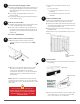
Product Labels
WARNING: Hot surface.
DANGER: Refer to safety instructions.
DANGER: Risk of electric shock.
Safety Instructions
General Safety
DANGER: Before installing or using the Enphase Micro-
inverter, read all instructions and cautionary markings in
the technical description, on the Enphase Microinverter
System, and on the photovoltaic (PV) equipment.
DANGER: Risk of electric shock. Do not use Enphase
equipment in a manner not specied by the manufac-
turer. Doing so may cause death or injury to persons, or
damage to equipment.
DANGER: Risk of electric shock. Be aware that installa-
tion of this equipment includes risk of electric shock. Do
not install the AC junction box without rst removing AC
power from the Enphase System.
DANGER: Risk of electric shock. The DC conductors
of this photovoltaic system are ungrounded and may be
energized.
WARNING: Risk of electric shock. Always de-energize
the AC branch circuit before servicing. Never disconnect
the DC connectors under load.
WARNING: Risk of electric shock. Risk of re. Only use
electrical system components approved for wet locations.
WARNING: Risk of electric shock. Risk of re. Only
qualied personnel should troubleshoot, install, or re-
place Enphase Microinverters or the Engage Cable and
Accessories.
WARNING: Risk of electric shock. Risk of re. Ensure
that all AC and DC wiring is correct and that none of the
AC or DC wires are pinched or damaged. Ensure that all
AC junction boxes are properly closed.
WARNING: Risk of electric shock. Risk of re. Do not
exceed the maximum number of microinverters in an AC
branch circuit as listed in this guide. You must protect
each microinverter AC branch circuit with a 20A maxi-
mum breaker.
+
WARNING: Do not connect Enphase Microinverters
to the grid or energize the AC circuit(s) until you have
completed all of the installation procedures and have re-
ceived prior approval from the electrical utility company.
✓
NOTE: To ensure optimal reliability and to meet warranty
requirements, install the Enphase Microinverters and
Engage Cable according to the instructions in this guide.
✓
NOTE: Perform all electrical installations in accordance
with all applicable local electrical codes and the National
Electrical Code (NEC), ANSI/NFPA 70.
✓
NOTE: The AC and DC connectors on the cabling are
rated as a disconnect only when used with an Enphase
Microinverter.
✓
NOTE: Protection against lightning and resulting voltage
surge must be in accordance with local standards.
✓
NOTE: Many PV modules have a central stiffening
brace. In these cases, do not position the connector
and microinverter at the exact center of the PV module.
Instead, position the drop connectors so that the con-
nectors do not conict with the braces.
✓
NOTE: Completely install all microinverters and all sys-
tem AC connections prior to installing the PV modules.
Safety and Advisory Symbols
DANGER! This indicates a hazardous situation, which if
not avoided, will result in death or serious injury.
+
WARNING! This indicates a situation where failure to
follow instructions may be a safety hazard or cause
equipment malfunction. Use extreme caution and follow
instructions carefully.
WARNING! This indicates a situation where failure to
follow instructions may result in burn injury.
✓
NOTE: This indicates information particularly important
for optimal system operation. Follow instructions care-
fully.
SAFETY
®