HD-TVI Speed Dome User Manual
HD-TVI Speed Dome User Manual ii Regulatory Information FCC Information Please take attention that changes or modification not expressly approved by the party responsible for compliance could void the user’s authority to operate the equipment. FCC compliance: This equipment has been tested and found to comply with the limits for a Class A digital device, pursuant to part 15 of the FCC Rules.
HD-TVI Speed Dome User Manual iii Safety Instruction These instructions are intended to ensure that the user can use the product correctly to avoid danger or property loss. The precaution measure is divided into ‘Warnings’ and ‘Cautions’: Warnings: Serious injury or death may be caused if any of these warnings are neglected. Cautions: Injury or equipment damage may be caused if any of these cautions are neglected.
HD-TVI Speed Dome User Manual iv Cautions: Make sure the power supply voltage is correct before using the product. Do not drop the product or subject it to physical shock. Do not install the product on vibratory surface or places. Do not expose it to high electromagnetic radiating environment. Do not aim the lens at the strong light such as sun or incandescent lamp. The strong light can cause fatal damage to the product.
HD-TVI Speed Dome User Manual v Table of Contents Chapter 1 1.1 1.2 Description ............................................................................................................................... 1 Functions .................................................................................................................................. 1 Chapter 2 2.1 2.2 2.3 2.4 Overview ..................................................................................................................
HD-TVI Speed Dome User Manual 1 Chapter 1 Overview 1.1 Description Integrated with the built-in pan/tilt unit, the HD-TVI speed dome features highly sensitive response and reliable performance. The speed dome can be adopted in various surveillance fields with its full-integral functions and features, such as corridor, large venue, meeting room, station, neighborhoods, etc. 1.2 Functions The functions vary according to the different models of the speed dome.
HD-TVI Speed Dome User Manual 2 In manual tracking mode, when a target object goes directly beneath the dome, the video will be automatically flipped 180 degrees in horizontal direction to maintain continuity of tracking. This function can also be realized by auto mirror image depending on different camera models. Privacy Mask This function allows you to block or mask certain area of a scene, for preventing the personal privacy from recording or live viewing.
HD-TVI Speed Dome User Manual 3 iris are in auto status during the pattern is being memorized. Power Off Memory The dome supports the power off memory capability with the predefined resume time. It allows the dome to resume its previous position after power is restored. Time Task A time task is a preconfigured action that can be performed automatically at a specific date and time.
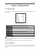
HD-TVI Speed Dome User Manual 4 Chapter 2 Getting Started 2.1 Power-up Action After the speed dome is power-on, it will perform a series of self-test actions. The interface will be shown as below: XXXXX SN ADDRESS COM MODE XXXXXXXXX 0 2400.8.1 PROTOCOL FIRMWARE HARDWARE AUTO MATCH X.XX X.XX BUILD DATE PAN SUCCESS TILT SUCCESS XX XX XX Figure 2-1 Original Interface Table 2-1 Descriptions of the original interface SN The serial No. of the speed dome, which is unique.
5 HD-TVI Speed Dome User Manual Panning and tilting: Click the direction buttons to control the pan and tilt movement of the speed dome. Zooming: Click the ZOOM+ and ZOOM- buttons to control the zooming. Focusing: Click the FOCUS+ and FOCUS- buttons to adjust the focus. Iris: Click the IRIS+ and IRIS- buttons to adjust the iris. 2.3 System-defined Presets Purpose: The section lists the system-defined presets with special functions.
HD-TVI Speed Dome User Manual 6 Alarm: When an alarm is triggered, the corresponding information will be displayed. Time: Displayed as Day/Month/Year/Day of Week/Hour/Minute. It supports 24-hour time system. Preset Label: After you call the configured preset, the preset number is displayed if the lens moves to the certain place where you’ve set a preset for. Zone: Display the zone title. Address: Display the address of the speed dome. Error Rate: Display the error rate of the speed dome.
7 HD-TVI Speed Dome User Manual Chapter 3 Menu Operation The menu operation part is only for your reference. The actual display may vary with your camera model. You can click the left and right direction buttons in the PTZ control panel via the web browser of the DVR to enter the next page or return to the previous page of the submenu if more than one page is available.
HD-TVI Speed Dome User Manual 8 3.1 Accessing and Operating the Menu To call the main menu: Steps: 1. Connect the video and RS-485 cables of speed dome to a DVR. 2. Visit the DVR via the web browser. 3. View the live video of the speed dome. 4. For PELCO-P/D and other private PTZ protocols, call preset 95 from the preset list in the PTZ control panel of the DVR.
9 HD-TVI Speed Dome User Manual information shown after the power-up action. Please refer to Section 2.1 for more details. Enter the system information display menu: MAIN MENUS > SYS INFO SYS INFO XXXXX 0 ADDRESS COM MODE PROTOCOL 2400.8.1 AUTO MATCH FIRMWARE HARDWARE 3.50 1.00 BUILD DATE BACK SYS INFO CAM VERSION PARAM DATE 3.23-680 0 0 0 TEMPERATURE VIDEO OUT 19 01 17 BACK EXIT 30 TVI EXIT Figure 3-3 System Information Information on this menu cannot be edited.
HD-TVI Speed Dome User Manual 10 Dome address settings To Set the Soft Address of the Speed Dome If the SOFT ADDR ACT is set to ON, the soft address is the valid address for connecting the speed dome. If the SOFT ADDR ACT is set to OFF, the hard address set by the DIP switch is the valid address of the speed dome. Before you set the soft address of the speed dome, you need to confirm that it is within the control range of the control device (e.g. the DVR).
HD-TVI Speed Dome User Manual Y- M- D 19 01 05 H- M- S 15 08 05 11 IRIS +: OK IRIS -: CANCEL Figure 3-5 Set the System Time Zero Angle Configuration Purpose: You can define the zero angle of the speed dome on the ZERO ANGLE submenu. Steps: 1. Move the cursor to ZERO ANGLE using the direction buttons and click IRIS+ to enter. 2. Click the left/right/up/down direction buttons to adjust the monitor angle of the speed dome. 3. Click IRIS+ button to confirm the settings and exit.
12 HD-TVI Speed Dome User Manual DISPLAY SETTINGS ZOOM SHOW P T SHOW OFF OFF TIME SHOW PRESET SHOW ZONE SHOW OFF OFF OFF ADDRESS SHOW ERROR RATE SHOW BACK OFF OFF EXIT Figure 3-6 Display Settings The speed dome shows the viewing direction when you manually control it to rotate. Table 1-1 Viewing Direction Display Display N NE E SE S SW Indication North Northeast East Southeast South Southwest W West NW Northwest The north direction refers to the angle zero.
13 HD-TVI Speed Dome User Manual Power Memory Settings The dome can resume its previous PTZ status after it restarted from a power-off when it stops at a position longer than the predefined time. You can set the memory time to 10S, 30S, 60S, 180S, and 300S. Coaxitron Control The Coaxial transmission function can be enabled to transmit the RS485 signal along with the video signal via the BNC cable.
14 HD-TVI Speed Dome User Manual CAMERA WHITE BALAN RED CAMERA CAMERA ATW 64 MIN. ZOOM LIMIT CHROMA SUPPRESS 1.0 2 BLUE IMAGE FLIP 64 OFF SATURATION CONTRAST 3 2 FOCUS LIMIT 2D DNR 5M 1 SCENE MODE HLC INDOOR 0 3D DNR 2 BACK EXIT SHARPNESS COMP BACK EXIT GAIN LIMIT 15 DEFOG OFF INIT LENS OFF 2 BACK EXIT Figure 3-7 Camera Settings Task 1: Configure the focus settings. Setting the focus mode Steps: 1. Move the cursor to FOCUS using the direction buttons and click IRIS+ to enter. 2.
HD-TVI Speed Dome User Manual 15 You can define the speed at which the lens changes from full wide zoom to the optical zoom. Steps: 1. Move the cursor to ZOOM SPEED using the direction buttons and click IRIS+ to enter. 2. Click up/down direction buttons to choose the speed from HIGH (default), MEDUIM and LOW. 3. Click IRIS+ button to confirm. Task 3: Configure the IR cut filter. There are two parameters available for IR cut filter configuration. 1. IR cut filter. It can be set as AUTO, DAY or NIGHT.
HD-TVI Speed Dome User Manual 16 responding to the lighting conditions. It is the default mode. IRIS: User-defined iris value, auto shutter and auto gain. It is the iris-priority mode. Please define the iris value according to related content in this section if you choose IRIS mode. SHUTTER: User-defined shutter speed, auto iris and auto gain. It is the shutter-priority mode. Please define the shutter speed according to related content in this section if you choose SHUTTER mode.
HD-TVI Speed Dome User Manual 17 (auto-tracking) and HAUTO (half-auto). AUTO: In Auto mode, the dome retains color balance automatically according to the current color temperature. INDOOR, OUTDOOR: These two modes are for indoor use and outdoor use respectively. SELFDEF: In this mode, you can adjust the color temperature manually to meet your own demand. In SELFDEF mode, you need to adjust the RED and BLUE values manually.
HD-TVI Speed Dome User Manual 18 Saturation Saturation value indicates the brightness of the color. The higher the saturation, the brighter the color is. The saturation function is supported by certain speed dome model series. Scene Mode Select the scene mode as INDOOR or OUTDOOR, and the default image settings will be changed according to the selected scene mode. Contrast Contrast is the degree of difference between the darker and lighter parts of the image.
HD-TVI Speed Dome User Manual PRIVACY MASK MASK NO. MASK STATUS SET MASK CLEAR MASK BACK 19 1 OFF EXIT Figure 3-8 Privacy Mask Configuration Menu 2. Choose the privacy mask number: Steps: (1) Move the cursor to MASK NO. and click IRIS+ to enter the editing mode. (2) Click the up and down direction buttons to select a mask number for configuration. (3) Click IRIS+ again to confirm and exit the editing mode. 3. Configure the position and size of the privacy mask.
HD-TVI Speed Dome User Manual 20 If no privacy mask has been configured, you cannot set the status to ON. 5. Delete the privacy mask. You can enter the CLEAR MASK menu to delete the all the configured privacy mask. 3.3.3 Configuring Output Standard Purpose: The video output standard, including resolution and frame rate, can be changed according to the actual requirement. Steps: 1. Move the cursor to enter the Video Settings submenu: MAIN MENUS > SYS SETTINGS > VIDEO SETTING 2.
HD-TVI Speed Dome User Manual 21 Set the electricity level of the IR LED. The N/M LED CURRENT and the FAR LED CURRENT refer to the electricity level of the near/middle IR LED and far IR LED correspondingly. Set the parameters for reference zoom. The value of REFERENCE ZOOM can be adjusted from 2 to 10. Set the parameters of LED control.
HD-TVI Speed Dome User Manual 22 Proportional Pan When the speed dome is zooming in/out, you can enable the proportional pan function to automatically reduce or increase the panning and tilting speed according to the zooming amount. This function enables the speed dome to trace the object at a proper speed when the speed dome is zooming and the monitored scene is narrowed (zoom in) or enlarged (zoom out). You can set PROPORTIONAL PAN to ON or OFF to enable/disable the function.
HD-TVI Speed Dome User Manual 23 Steps: 1. Move the cursor to ENABLE LIMIT and click FOCUS+ to set it ON to enable this feature. Click IRIS+ to confirm the new settings. 2. Move the cursor to SETTING STOPS and click IRIS+. You will see the message SET LEFT LIMIT on the screen. 3. Click the direction buttons in the PTZ panel to configure the left limit. Click IRIS+ to confirm the new settings. 4. Follow the prompts to configure the right, up and down limits on the menu.
HD-TVI Speed Dome User Manual 24 The system-defined presets will be displayed on this submenu and they are not editable. 3. Set the preset position. Move the cursor to PRESET PTZ and click IRIS+ to edit the preset position. Use the direction buttons to move the speed dome to find the desired scene/position, and then press IRIS+ to confirm the settings and return to the previous menu, or press IRIS- to cancel. The preset position settings will be restricted by the limits if they are defined. 4.
HD-TVI Speed Dome User Manual 25 DVR to 15s, corresponding to the dome it would be 140s. Refer to the interface for more details. However, if you select EQUAL, they will be exactly the same. 4. Edit the patrol. Steps: (1) Move the cursor to EDIT PATROL and click IRIS+ to enter editing mode. NO.
HD-TVI Speed Dome User Manual 26 3.4.4 Configuring Patterns Purpose: A pattern is a memorized, repeatable series of pan, tilt, zoom and preset movements that can be recalled by a command or automatically performed by a configured function (alarm, park, time task, and power-up). Steps: 1. Move the cursor to enter the PATTERNS submenu: MAIN MENUS > SYS SETTINGS > PATTERNS PATTERNS PATTERN NO. 1 EDIT PATTERN PREVIEW CLEAR PATTERN REMAINING BACK 100 EXIT Figure 3-15 Pattern Configuration Menu 2.
HD-TVI Speed Dome User Manual 27 REMAIN MEMORY indicates the remaining memory of the speed dome for configuring the patterns. When it reaches 0, no more patterns can be configured. You can also see the remaining memory shown under PATTERNS menu as REMAINING. The pan/tilt movements and the lens operations cannot be memorized simultaneously. 4. Preview the pattern. Enter the PREVIEW menu to preview the current pattern. 5. Call the defined pattern.
HD-TVI Speed Dome User Manual 28 (2) Click the up/down direction buttons to select the number of the task which is to be configured. (3) Click IRIS+ again to confirm the settings and exit the editing mode. 3. Set the task status. Steps: (1) Move the cursor to TASK STATUS and click IRIS+ to enter the editing mode. (2) Click the up/down direction buttons to set the task status to ON. (3) Click IRIS+ again to confirm the settings and exit the editing mode of this column.
HD-TVI Speed Dome User Manual 29 3.4.6 Configuring Zone Purpose: A zone is a panning and tilting area defined by the left/right limits. You can configure the zones in ZONES submenu. You can define a zone when the targeted surveillance scene is limited. Steps: 1. Move the cursor to enter the zone configuration submenu: MAIN MENUS > SYS SETTINGS > ZONES ZONES ZONE NO. 1 EDIT ZONE ZONE STATUS SCAN STATUS CLEAR ZONE BACK ON ON EXIT Figure 3-19 Zone Configuration 2.
HD-TVI Speed Dome User Manual 30 3.4.7 Configuring Smart Settings Purpose: Set the SMART SETTINGS to ON to automatically track the moving object, meanwhile adjusts the focus and the position to set the target in the center of the view. Steps: 1. Move the cursor to enter the smart setting submenu: MAIN MENUS > SYS SETTINGS > SMART SETTINGS SMART SETTING TRACK ACTIVE OFF TRACK TIME 100 TRACK ZOOMRATIO BACK EXIT Figure 3-20 Smart Setting 2. Set the tracking time.
31 HD-TVI Speed Dome User Manual CLEAR SETTINGS CLEAR ALL PRESETS CLEAR ALL PATROLS CLEAR ALL PATTERNS CLEAR ALL MASKS CLEAR ALL ZONES CLEAR ALL TIME TASK BACK EXIT Figure 3-21 CLEAR SETTINGS 2. Move the cursor to the item you want to clear, and click IRIS+ to validate the settings. 3. Move the cursor to the and click IRIS+ to diagnose the temperature exception, video exception, voltage exception, etc. 3.
HD-TVI Speed Dome User Manual 32 (1) Move the cursor to ALARM NO. and click the IRIS+ to enter the editing mode. (2) Click the up and down direction buttons to select the number of the alarm which is to be configured. (3) Click IRIS+ again to confirm and exit editing mode of this column. 3. Move the cursor to ALARM SETTING and click the IRIS+ to enter the setting alarm submenu. 4. Configure the alarm input. Steps: (1) Move the cursor to ALARM INPUT and click the IRIS+ to enter the editing mode.
HD-TVI Speed Dome User Manual 33 cleared. 4. Resume the dome activity. You can set ALARM RESUME to ON to enable the speed dome to resume its previous activity after the triggered actions finished. If the speed dome is moving when a linkage action is triggered, it will stop at the current position and resume from this position after the linkage action is finished. The speed dome can be configured to resume the PTZ positions, focus, and iris value. 3.5.
HD-TVI Speed Dome User Manual 34 3.6 Others 3.6.1 Restoring Default Dome Settings Purpose: You can reset all dome settings to factory default parameters as shown in below. Dome settings are mainly of PTZ parameters and alarm parameters, and also include some system settings, e.g. dome address. Enter default dome settings menu: MAIN MENUS > RESTORE DEFAULTS Click IRIS+ to restore the dome settings to the default value, or click IRIS- to exit. 3.6.
HD-TVI Speed Dome User Manual 35 Appendix Appendix 1 Lightning & Surge Protection This product adopts TVS plate lightning protection technology to avoid damage caused by pulse signal that is below 3000W, like instantaneous lighting stroke, surging, etc. According to the actual outdoor situation, necessary protection measures must be taken, besides ensuring the electrical safety. The distance between signal transmission wires and High-voltage equipment or high-voltage cable is at least 50m.
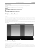
36 HD-TVI Speed Dome User Manual Appendix 2 RS485 Bus Connection General Property of RS485 Bus According to RS485 industry bus standard, RS485 is a half-duplex communication bus which has 120Ω characteristic impendence, the maximum load ability is 32 payloads (including controller device and controlled device). RS485 Bus Transmission Distance When using 0.56mm (24AWG) twisted-pair line, according to different baud rate, the maximum transmission distance theory table is shown as below: Table A-1 Max.
HD-TVI Speed Dome User Manual 37 Figure A-4 Star Shape Connection For such case, the best way is adding a RS485 distributor. This product can effectively change the star-shape connection to which satisfies the requirement of RS485 industry standard, in order to avoid those problems and improve the communication reliability. Show as figure 5. Figure A-5 RS485 Distributor Troubleshooting of RS485 communication Problem Possible Reasons To Solve the Problem 1. Adjust the address and baud 1.
HD-TVI Speed Dome User Manual Problem dome can be controlled but not smoothly. Possible Reasons To Solve the Problem tightly. 2. RS485+ or RS485-wire is 2. Change a RS485 wire. broken. 3. The speed dome is too far away 3. Add a terminal resistor. from the remote control device. 4. Too many speed domes are 4. Add a RS485 distributor. connected.
39 HD-TVI Speed Dome User Manual Appendix 3 24 VAC Wire Gauge & Transmission Distance The following table describes the recommended maximum distance adopted for the certain wire gauge when the loss rate of 24 VAC voltage is less than 10%. For the AC driven device, the maximum voltage loss rate is 10% allowable. For example, for a device with the rating power of 80VA which is installed at a distance of 35 feet (10 m) away from the transformer, then 0.8000mm is required as the minimum wire gauge.
40 HD-TVI Speed Dome User Manual Appendix 4 Wire Gauge Standards Bare Wire Gauge(mm) 0.750 0.800 0.900 1.000 1.250 1.500 2.000 2.500 3.000 American Wire Gauge AWG 21 20 19 18 16 15 12 British Wire Gauge SWG 21 20 19 18 17 14 Cross-sectional Area of Bare Wire (mm2) 0.4417 0.5027 0.6362 0.7854 1.2266 1.7663 3.1420 4.9080 7.
41 HD-TVI Speed Dome User Manual UD15214N