
Installation Instructions


Ensemble Communications Inc.
3-8
Operator’s Guide to the Fiberless System
Figure 3-2. Proper Mounting of Two Antennas on Separate Poles
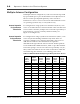
Figure 3-3. Minimum Angle Separation
Use Table 3-2 and the following figures to calculate roof-mount
requirements to clear the first Fresnel zone for nearby obstructions.
D
Channel
N
Channel
N+2
Assumptions:
Antennas pointed in parallel
Minimum of two channels
separation
Spacing dependent on
modulation rate and antenna
beam width
·See Table 3-1 for horizontal
separations for
nonsynchronous transmission.
Separation for synchronous
transmission is 0.5 m (1.65 ft).
D
Channel
N
Channel
N+2
Assumptions
Antennas separated by
angle D
Spatial separation D
Minimal angle and
separation dependent on
modulation rate and
antenna beamwidth
See Table 3-1 for
horizontal separations for
nonsynchronous
transmissions.
Table 3-2: Minimum Roof Clearance
Frequency D1 (meters) Minimum R (cm)
24 1 ~0
24 10 1.12
24 100 3.53
41 1 ~0