Preface Welcome! Congratulations and thank you for your purchase of the ENSONIQ ASR-10 Advanced Sampling Recorder, another milestone in digital sampling keyboards. The ASR-10 revolutionizes the way sampling is integrated into a workstation, by including 24-bit dynamic effects processing and allowing the stereo audio input to be monitored, sampled, and resampled through the effects. And only ENSONIQ offers all the expressive control that turns a sampler into a truly musical instrument.
Preface ASR-10 Musician’s Manual Audio Track Recording Capability Version 2 O.S. adds two tracks of digital audio recording capability to the ASR-10. Audio Tracks can be recorded directly into RAM (RAMTracks™) or directly to a SCSI storage device (hard disk, removable media, etc.) via the optional SP-3 SCSI Interface (DiskTracks™). Now you can combine live performances with MIDI sequenced tracks for full production recording within the ASR-10.
Preface Thank-you again for choosing ENSONIQ.
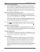
Preface ASR-10 Musician’s Manual Power 1 2 Insert the line cord into the line receptacle on the back of the ASR-10 (2), next to the power switch (1). Plug the other end of the cable into a grounded AC outlet. The proper voltage for your ASR10 is listed on the Serial Number label on the rear panel. Turn the ASR-10 power on and make sure the display lights up. If not, check your connections and power source.
Preface Ground Loops Sometimes currents flowing through the ground line generate a signal seen by another part of the circuit sharing the same ground. In other words, if there are two identical signal paths within a circuit, they can form a loop which can result in hum and/or noise. If you are using equipment that has 3-prong “grounded” AC power cords, you may suffer from a ground loop resulting from the interconnection of this equipment.
Preface ASR-10 Musician’s Manual Amplification Connect the Main Audio Outputs of the ASR-10 to the line level inputs of a mixer, instrument amplifier, stereo, or any other sound system, using 1/4 inch audio cables. If your system is stereo, connect the Left and Right Main Outputs to two channels of your mixer, stereo, etc. If it’s mono, use either of the Main Audio Outputs, but make sure nothing is plugged into the other output.
Preface Care and Feeding of the Disk Drive The ASR-10’s built-in disk drive is used to store all your Instruments, Banks, and Sequencer data, as well as System Exclusive messages from other MIDI devices. The ASR-10 uses a Quad-density disk drive that can store 1600 Kilobytes of data on a Double-Sided High-Density (DSHD) 3.5” micro-floppy disk and 800 Kilobytes of data on a Double-Sided Double-Density (DSDD) 3.5” micro-floppy disk.
Preface ASR-10 Musician’s Manual Backing-up the O.S. Disk Since floppy disks are vulnerable to the affects of magnetic fields, we highly recommend making back-up copies of your O.S. disk. Doing so can save time and frustration in the unlikely event that the O.S. disk becomes damaged. Since the tutorial files and the additional 44.1 kHz effect algorithms are on the O.S. disk, you will need a HD (high density) disk to save all of the information. We’ll use the COPY FLOPPY DISK command to back up the disk.
Preface Accessories These optional accessories are available from your Authorized ENSONIQ Dealer: • OEX-6sr Output Expander — The OEX-6sr gives the ASR-10 six additional outputs, grouped in three stereo pairs in addition to the built-in stereo outputs. Each WaveSample, or an entire instrument/track can be assigned to any of the stereo pairs and panned within the stereo field.
Preface ASR-10 Musician’s Manual Need More Help? Whether you’re an aspiring programmer looking for additional information about basic sampling techniques and MIDI theory, or a professional sound designer working with advanced applications, you may want more detailed information that is beyond the scope of this manual. The following books can help enhance your understanding of sampling, synthesis, MIDI, and related topics.
Preface Monthly Magazines The following magazines offer many specific articles and columns that can provide a plethora of useful information.
Section 1 — Controls & Architecture This section provides an introduction to the ASR-10’s many controls and rear panel connections, a conceptual overview of the system, a guide to understanding memory, and a discussion of editing various types of parameters. We suggest you read this section carefully — it will help you get the most out of your ASR-10.
Section 1 — Controls and Architecture Note: ASR-10 Musician’s Manual If you are using a single foot switch (SW-2 or SW-6), the Edit/System•MIDI, LEFT FOOT SW parameter should be set to OFF. This will prevent unexpected behaviour. Remember that the Foot Switch jack is optimized for use with a dual foot switch (SW-10), and when a single foot switch is connected, it behaves like the Right Foot Switch. When the SW-2 is connected to the Foot Switch jack: It acts as the Sustain Pedal.
Section 1 — Controls and Architecture 8) Pedal•CV This jack is for connecting an optional ENSONIQ Model CVP-1 Control Voltage Foot Pedal, which is assignable as a modulator to various parameters within the ASR-10. The pedal gives you a handy alternative modulation source when, for example, you would want to use the Mod Wheel but both hands are busy.
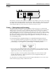
Section 1 — Controls and Architecture ASR-10 Musician’s Manual Rear Panel Connections Cont’d. Digital I/O SCSI Output Expander 10 11 Mic Line Input Level Out In 9 12 13 Audio Input B/Right A/Left Main Out Right/Mono Left/Mono 15 14 Phones 16 9) Digital I/O — Input/Output The DI-10 Digital I/O Interface (S/PDIF) provides direct Digital Input and Output connection to and from the ASR-10 using RCA-type connectors. The Digital Output will provide direct 44.
Section 1 — Controls and Architecture 14) Audio Input — B/Right and A/Left These jacks are the Right and Left Audio Inputs into the ASR-10 for sampling or Audio Track monitoring of external analog audio sources. SPECS: 140 KOhm input impedance, AC coupled. The Audio Inputs have 2 ranges: Line and Mic. With the Mic/Line switch set to Line, the ASR-10 will accommodate signals from +15.5dBV (Input Level Trim control fully counterclockwise) to -16.5dBV (Input Level Trim control fully clockwise).
Section 1 — Controls and Architecture ASR-10 Musician’s Manual Front Panel Controls Almost everything you do on the ASR-10 — whether it’s selecting a sound, editing that sound, adjusting the tuning, etc.
Section 1 — Controls and Architecture 3) Page Buttons Within each mode, the available disk files, commands, and parameters are organized into Pages. A page is selected by pressing one of these fourteen page buttons. Once you are on the correct page, you use the Data Entry Controls to scroll through the files, commands or parameters on the page. A given page will have different functions depending on the current mode. Each mode has a different set of pages available.
Section 1 — Controls and Architecture ASR-10 Musician’s Manual Additional Front Panel Controls 6 Left 7 Right 8 Sample FX Select Source Select FX Bypass Peak 5 Signal Input Level Record 1 2 3 4 5 6 7 8 Instruments Sequence Tracks Stop A B Audio Tracks Continue 10 11 9 Play 5) Display The ASR-10 Display is divided into two main sections: the Indicator Lights in the top half of the window and the 22-character Alphanumeric Display at the bottom of the window.
Section 1 — Controls and Architecture 8) FX Select•FX Bypass Button This button acts as the “master” control switch for the built-in effects, determining which, if any effect will be used and how it will interact with the instruments that reside in the internal memory. The controls on this page also determine the current sample rate and polyphony.
Section 1 — Controls and Architecture ASR-10 Musician’s Manual Performance Controllers The ASR-10 features a number of real-time performance controllers that can modify sounds as you play for maximum expressiveness. Three of the most important controllers are located to the left of the keyboard: Patch Select Buttons Pitch Bend Wheel Modulation Wheel • PATCH SELECT BUTTONS — These two buttons are used to select alternate groups of voices (called Layers) within a sound.
Section 1 — Controls and Architecture Pressure (After-touch) Another important controller is Pressure. Pressure (often called after-touch) is a modulator that allows you to change the sound in various ways by pressing down harder on a key or keys after the initial keystrike. The ASR-10 keyboard is capable of generating two types of pressure — Channel Pressure and Poly-Key™ Pressure.
Section 1 — Controls and Architecture ASR-10 Musician’s Manual Architecture “Booting” the ASR-10 Insert the power cord into the line receptacle on the back of the ASR-10, next to the power switch. Plug the other end of the cable into a grounded AC outlet. The proper voltage for your ASR-10 is listed on the Serial Number label on the rear panel. Turn the ASR-10 power on and make sure the display lights up. If not, check your connections and power source. The ASR-10 Operating System (O.S.
Section 1 — Controls and Architecture Memory Disk Memory vs. Internal Memory The instruments, banks, and sequences that the ASR-10 plays are stored on 3.5” micro-floppy disks.
Section 1 — Controls and Architecture ASR-10 Musician’s Manual What is a SIMM? SIMM is an acronym which stands for Single In-line Memory Module. SIMMs have become the industry standard used by most computers (both IBM and Mac compatible) to expand the computer’s memory. Because of this, SIMMs are readily available in most computer software stores, and from mail order organizations. The ASR-10 memory, like a computer, is also expanded using SIMMs.
Section 1 — Controls and Architecture You will notice that there are two slots with SIMMs installed, and two slots that are empty. These empty slots are called Expansion SIMM Slots, and are used for adding additional SIMMs (when expanding the memory). Directly above the Standard SIMM Slots, you will find the Memory Expansion Jumper. About the Memory Expansion Jumper The Memory Expansion Jumper allows you to access the information in the Expansion SIMM Slots.
Section 1 — Controls and Architecture ASR-10 Musician’s Manual About the SIMM Socket The SIMM socket uses the pins on the end of the latching posts to hold the SIMM in place. The alignment notch on the SIMM prevents it from being installed backwards. Once installed, the retaining posts hold the SIMM in place securely, preventing it from dropping out of the socket inside the ASR-10.
Section 1 — Controls and Architecture Proper SIMM Installation Retaining Post Retaining Post • Reinstall the trap door with the original screws. To verify that you’ve expanded your memory correctly, after powering up the ASR-10, press Edit, then System•MIDI and scroll until the display shows FREE SYSTEM BLOCKS= (expanded memory amount in blocks). See the memory allocation chart (found earlier) for the proper number of blocks for each configuration.
Section 1 — Controls and Architecture ASR-10 Musician’s Manual information concerning the number of blocks, or noise and distortion. • If the jumper is not moved from the “STD” position to the “EXP” position, no memory in the expansion slots will be recognized. The wrong number of blocks will be displayed on the Edit/System•MIDI page. • If the jumper is moved from the “STD” to the “EXP” position and there are no SIMMs in the expansion slots, the system will not boot up (display will be blank).
Section 1 — Controls and Architecture About Instruments We refer to ASR-10 sounds as Instruments. A grand piano, an electric bass, a multi-sampled drum set, a complete string section — each of these would be an example of an instrument. You can load up to eight instruments into the ASR-10, memory permitting, and have instant access to any or all of them. Each instrument contains four different Patches that are selected with the Patch Select buttons.
Section 1 — Controls and Architecture LOAD INST ASR-10 Musician’s Manual STOP Once the instrument has been loaded, the display briefly shows “FILE LOADED.” The left red LED above the Instrument•Sequence Track button stops flashing and remains solidly lit, indicating that there is now an instrument loaded in that location which can be selected by pressing that button.
Section 1 — Controls and Architecture About Banks Banks provide a way to load a whole group of instruments and sequences into the ASR-10 with a few button presses. When you save a bank to disk, it is like taking a “snapshot” of the contents of the ASR-10 Internal memory — the bank file contains information about which instruments are loaded into which of the eight Instrument•Sequence Track locations, and which song and sequences (if any) are currently loaded in Internal Memory.
Section 1 — Controls and Architecture ASR-10 Musician’s Manual • Press Enter•Yes. The ASR-10 will resume loading until completed, or until the point when it needs another disk. • When it has finished loading the instruments, the ASR-10 will load the song (if any) and then set up any copied instruments included in the bank. Playing Instruments • First, press Load until LOAD is solidly lit in the display to make sure you are in LOAD Mode.
Section 1 — Controls and Architecture Note: Instruments can be played from an external MIDI controller, without being selected, when Edit/System•MIDI, MIDI IN MODE=MULTI or MONO-B see Section 2 — System•MIDI for details. Tip: When TRANSMIT ON = INST CHAN, on the Edit/System•MIDI page, editing the VOLUME value will transmit MIDI Volume messages (Controller #7) on the selected Instrument•Sequence Track’s MIDI OUT CHANNEL (on the Edit/Instrument page).
Section 1 — Controls and Architecture ASR-10 Musician’s Manual Now all of #3 is showing: Numbers 1, 2 and 4 are partially showing, partially covered up. 3 2 1 4 If we now bring #4 to the top of the pile, Numbers 1 and 2 are still partially visible, but #3 is completely covered up. 3 1 4 2 So it is with instruments loaded into the ASR-10 in Load mode. When you select an instrument, it is brought to the top of the pile.
Section 1 — Controls and Architecture If you select the piano, it will play over the whole keyboard, covering up the bass entirely: Piano Bass Now you select the bass. This brings it to the top of the pile, and it covers up the piano, but only in the region where their ranges overlap (the bottom two octaves): Bass Piano If you play now, you will hear the bass in the bottom two octaves and the Piano over the rest of the keyboard.
Section 1 — Controls and Architecture ASR-10 Musician’s Manual Loading Sequencer Data There are two ways that ASR-10 Sequencer data can be stored on a disk: • SONG File. A song file contains a song and all its related sequences. Loading a song file from disk will completely erase the current contents of the ASR-10 sequencer memory, replacing whatever is there with the song and sequences from the disk file. • SINGLE SEQUENCE File. This type of file contains just one sequence.
Section 1 — Controls and Architecture Selecting a Sequence/Song Press the Edit button, then the Seq•Song button. The following screen will appear: STOP SEQ EDIT Current Sequence or Song Bar and Beat Location within current Sequence or Song This screen is where you select a sequence or the song. With the selected sequence or song underlined (as shown above), use the Up/Down Arrow buttons or the Data Entry Slider to select a different sequence or song.
Section 1 — Controls and Architecture ASR-10 Musician’s Manual Saving Sequencer Data Saving a Single Sequence to Disk Use the SAVE CURRENT SEQUENCE command to save a single sequence. • On the Edit/Seq•Song page, select the sequence you want to save. • Insert a formatted disk into the drive. • Press Command, then press Seq•Song. • Press the Left or Right Arrow button until the display reads SAVE CURRENT SEQUENCE. • Press Enter•Yes.
Section 1 — Controls and Architecture Saving a Song (along with all Sequences) to Disk Once you have created a song or made changes to an existing one, you can save the song to a formatted ASR-10 disk. In addition to saving the song itself, the SAVE SONG + ALL SEQS command saves all the individual sequences currently in memory (whether they are part of the song or not). To save a song: • Insert a formatted disk into the drive. • Press Command, then press Seq•Song.
Section 1 — Controls and Architecture ASR-10 Musician’s Manual Managing Your System Headroom The ASR-10’s 16-bit stereo output converters provide 96dB of dynamic range. This figure of 96dB is referred to as the system headroom. Since the ASR-10 is capable of playing 31 notes of polyphony, this 96dB of system headroom must be divided amongst these 31 voices. If the output level of all sustaining voices exceeds 96dB, this will result in clipping.
Section 1 — Controls and Architecture Normal Sample Normal Sample Playback Attenuation Attenuated Sample -12dB Combined Samples still remain within the system headroom -12dB Drum Sample Drum Sample Playback without Attenuation The BOOST parameter should not be turned on for all WaveSamples. Sustaining sounds can remain at their peak volume for as long as a key is held down.
Section 1 — Controls and Architecture ASR-10 Musician’s Manual Parameter Illustrations The ASR-10 accesses parameters and commands through Pages. Each page is accessed by two button presses, the first being a Mode button and the second a Page button. Most parameters will also have a Direct-Dial number. This number can be pressed immediately after pressing the proper Mode and Page button to get to a specific parameter directly, bypassing scrolling with the Left/Right Arrow buttons.
Section 2 — System•MIDI These pages contain parameters and commands that affect the ASR-10 as a whole. Edit/System•MIDI Page This page contains global system and MIDI parameters. Due to the large number of parameters on this page, not all parameters have a direct dial number. Those that do will have that number listed in its parameter illustration. Parameters without direct dial numbers can be accessed with the Left/Right Arrow buttons.
Section 2 — System•MIDI EDIT SYSTEM•MIDI ASR-10 Musician’s Manual TOUCH (Velocity and Pressure Response) Press Edit / System•MIDI / scroll using the arrow buttons Allows you to adjust both the pressure and velocity response of the keyboard to match your playing style and technique. For each of the four velocity settings SOFT, MED, FIRM, HARD there are four pressure thresholds 1, 2, 3, 4, for a total of 16 available settings.
Section 2 — System•MIDI EDIT SYSTEM•MIDI LEFT FOOT SW Press Edit / System•MIDI / scroll using the arrow buttons When the optional SW-10 Dual Foot Switch is plugged into the rear panel Foot Switch jack, this page allows the Left Foot Switch to perform a variety of assignable functions. The Right Foot Switch is permanently dedicated to function as the Sustain pedal. • OFF — This setting makes the ASR-10 ignore the Left Foot Switch.
Section 2 — System•MIDI ASR-10 Musician’s Manual MIDI Parameters Few developments in recent years have had as great an impact on the way we make music as has the emergence of MIDI. Whether you are simply linking two keyboards together, playing a synth from a guitar controller, or driving a rack of samplers from a drum pad controller, MIDI makes it all possible. The evolution of MIDI has facilitated the merging of existing technologies and has inspired the creation of new technologies.
Section 2 — System•MIDI • When BASECHAN PRESSURE=OFF, no pressure will be transmitted via MIDI. • When BASECHAN PRESSURE=KEY, the ASR-10 will transmit the most expressive type of pressure — key pressure via MIDI. The ASR-10’s Poly-Key™ Pressure lets you modulate each note independently. If you press down on any given key within a chord, only that note will be affected by pressure—all other notes remain unmodulated.
Section 2 — System•MIDI ASR-10 Musician’s Manual MONO Modes MONO modes are particularly useful for driving the ASR-10 from a guitar controller, or any other application where having up to eight independent, monophonic channels is desirable. The ASR-10 offers two types of MONO mode operation: • MONO A is the mode you will probably use most often. This is the mode to use when you want to play the same sound on all the strings of your guitar controller.
Section 2 — System•MIDI EDIT SYSTEM•MIDI MIDI SYS-EX (ON/OFF) Press Edit / System•MIDI / scroll using the arrow buttons This parameter determines whether the ASR-10 will send and receive MIDI System Exclusive messages, such as remote programming instructions or WaveSample dumps. When OFF, the ASR-10 will neither transmit nor receive System Exclusive messages.
Section 2 — System•MIDI ASR-10 Musician’s Manual button, and send the ASR-10 a program change that is the file number +1 on the Instrument•Sequence Track’s Edit/Track MULTI-IN MIDI CHANNEL. To load a Bank file, send the ASR-10 a program change that is the Bank file number +1. When a program change is received, the ASR-10 will load the appropriate file from the currently selected storage device (FLOPPY, SCSI 0-7). Incoming MIDI program changes 101-128 will invoke Macros 0-27.
Section 2 — System•MIDI Although the range of this control is from 0 to 127, many of the values other than those listed above have no “approved” function, yet. They exist to provide flexibility and to accommodate future MIDI standards. EDIT SYSTEM•MIDI MULTI CONTROLLERS Press Edit / System•MIDI / scroll using the arrow buttons This parameter determines whether local controllers (such as the patch select buttons, volume pedal, mod wheel, etc.) will affect all tracks or only the selected track(s).
Section 2 — System•MIDI ASR-10 Musician’s Manual Command/System•MIDI Page Due to the large number of commands on this page, not all commands have a direct dial number. Those that do will have that number listed in its command illustration. Commands without direct dial numbers can be accessed with the Left/Right Arrow buttons. CMD SYSTEM•MIDI FORMAT FLOPPY DISK Press Command / System•MIDI / 0 Before you can save ASR-10 instruments, banks, or sequences to a disk it must be formatted.
Section 2 — System•MIDI CMD SYSTEM•MIDI COPY O.S. TO DISK Press Command / System•MIDI / 1 Use this command to put the ASR-10 Operating System (O.S.) on a new disk that you have formatted, or to update the Operating System on an existing disk with a newer version. Note: The Operating System can only be copied to a blank disk, or a disk (with or without sounds and sequences) that has an existing operating system on it. You cannot copy the Operating System to a disk that only has instruments or sequences.
Section 2 — System•MIDI CMD SYSTEM•MIDI ASR-10 Musician’s Manual SAVE GLOBAL PARAMETERS Press Command / System•MIDI / 2 The SAVE GLOBAL PARAMETERS Command saves the settings for the following parameters: • • • • • • • All Edit/System•MIDI parameters All Sample•Source Select parameters The current FX Select•FX Bypass page setting All Edit (audio) Track parameter settings The MULTI-IN MIDI CHAN settings on the Edit/Track page The Edit/Seq•Song CLOCK SOURCE, CLICK settings, and SEQ COUNTOFF mode The Sourc
Section 2 — System•MIDI CMD SYSTEM•MIDI CHANGE STORAGE DEVICE Press Command / System•MIDI / 5 Use this command to determine whether the ASR-10 will use floppy disk or an external SCSI Storage Device. • Select CHANGE STORAGE DEVICE. Press Enter•Yes. • Select LOAD DEVICE=FLOPPY/SCSI 0 through 7. • You must press Enter•Yes to change the storage device. Otherwise, you will get the COMMAND ABORTED message. • Press Enter•Yes. The display reads COMMAND COMPLETED.
Section 2 — System•MIDI ASR-10 Musician’s Manual destination disk is unformatted, the display will ask ERASE AND FORMAT DISK? Press Enter•Yes to format the disk. When formatting is complete, the drive will engage and the display will flash WRITING DEST DISK. • After writing to the destination disk, the display will read VERIFYING DEST DISK. If the copy is complete, then the display will read DISK COMMAND COMPLETED.
Section 2 — System•MIDI To save the Sys-Ex file to disk: • Insert a formatted disk into the ASR-10. • Pressing Enter•Yes displays FILENAME=SYS-EX FILE. You can name your Sys-Ex file by using the data entry controls, if you wish. • Press Enter•Yes. The display reads SAVING , then DISK COMMAND COMPLETED. • Pressing Cancel•No aborts the command. LOADING System Exclusive Data from Disk and SENDING to an External Device • Connect the MIDI Out of the ASR-10 to the MIDI In of the receiving device.
Section 2 — System•MIDI CMD SYSTEM•MIDI ASR-10 Musician’s Manual COPY SCSI DRIVE Press Command / System•MIDI / scroll using the arrow buttons This command enables you to copy the data from one SCSI Storage Device to another of the same capacity (they must have exactly the same capacity for the process to work) or copy data from one cartridge of a removable SCSI Storage Device to another cartridge.
Section 2 — System•MIDI CMD SYSTEM•MIDI BACKUP/RESTORE Press Command / System•MIDI / scroll using the arrow buttons The BACKUP/RESTORE command allows you to make a backup copy of all of the information on a SCSI Storage Device. If the drive later fails and must be reformatted, or if you are switching to another drive, you can restore the drive from the backup copy. • Press Command, then System•MIDI, and scroll until “BACKUP/RESTORE” appears in the display. • Press Enter•Yes.
Section 2 — System•MIDI ASR-10 Musician’s Manual BACKUP Note: If you are using removable cartridges as your backup storage device, you must boot the ASR-10 with a formatted cartridge in the drive. Otherwise, the ASR-10 will not recognize the drive as a valid device. Subsequent cartridges need not be formatted beforehand; they will be automatically formatted as part of the backup procedure.
Section 2 — System•MIDI RESTORE The RESTORE utility first checks the SCSI Storage Device to see if it needs formatting or erasing. If so, it will automatically format and erase the disk. Next, the ASR-10 displays: SYSTEM STOP CMD INSERT DISK #1 After you insert the first backup disk (or cartridge) and press Enter•Yes, the ASR-10 copies the OS (if necessary) from the backup disk. Then, it loads the BACKUP FILE and recreates all of the directories on the SCSI Storage Device.
Section 2 — System•MIDI CMD SYSTEM•MIDI ASR-10 Musician’s Manual CONFIGURE AUDIO TRACKS Press Command / System•MIDI / scroll using the arrow buttons SYSTEM STOP CMD This command enables and disables Audio Track playback and recording. It also determines whether Audio Tracks will be recorded direct-to-disk via the SCSI port, or whether they will reside in RAM and must be manually saved to disk as part of a SONG + ALL SEQS file.
Section 2 — System•MIDI Macros What Is a Macro? It may have occurred to you that with the large number of files that a SCSI Storage Device can contain, it would be nice to be able to get directly to a directory or specific file quickly rather than having to scroll through all your files. Macros allow you to do this. In the ASR-10, a macro is a shortcut command that allows you to get to a file or directory on your SCSI Storage Device (or floppy) with just two or three button presses.
Section 2 — System•MIDI Note: ASR-10 Musician’s Manual All macro operations are performed with the Load button held down, and take effect when the Load button is released. Loading a Macro File • Press Load then System•MIDI, and scroll to the macro file that you wish to load. • Press Enter•Yes to load a new set of 28 macros into the ASR-10. Creating a Macro • Find the file or directory to which you want to assign a macro.
Section 2 — System•MIDI “Direct Dialing” on CD-ROMs with Direct Macros ENSONIQ formatted CD-ROMs have a unique Direct-Macro number assigned to each individual file location (see the CD-ROM manual for Direct-Dial listings), and can be “direct dialed” — accessed directly through the use of its four-digit “Direct Macro” number. Note that these Direct Macros are used exclusively for locating Instrument files. Demos, banks, effects, songs, and sequences can be located in the normal way.
Section 3 — Instrument, Bank, & Preset Concepts This section offers a basic overview of the concepts involved in selecting, creating, editing, and understanding Instruments, Banks and Performance Presets. For more detailed descriptions of the actual parameters, refer to the following section. Instruments The ASR-10 keeps all its sounds in a format called an Instrument. This format is used for all disk storage. The internal structure of an Instrument has three levels: Instrument, Layer, and WaveSample.
Section 3 — Instrument, Bank, and Preset Concepts ASR-10 Musician’s Manual Loading an Instrument You can load up to eight different instruments into the ASR-10 at once (within the limits of memory). First, insert a disk containing one or more instrument files into the disk drive. • Press Load. The LOAD indicator flashes. • Press Instrument.
Section 3 — Instrument, Bank, and Preset Concepts Saving an Instrument to Disk After you have created a new ASR-10 instrument, or made changes to an existing instrument, you can save the instrument to a formatted ASR-10 disk with the following steps: • Insert a formatted disk into the drive. If you don’t have a formatted disk, format one before proceeding. • Press Command, then Instrument. This puts you on the Command/Instrument page, that contains all the instrument-related commands.
Section 3 — Instrument, Bank, and Preset Concepts ASR-10 Musician’s Manual instructions telling the ASR-10 what to load and where to load it. All the instruments and the song in a Bank must be saved to disk separately (or loaded in from a disk with a proper Disk Label ID) prior to saving the Bank. • Any instruments already loaded into locations not affected by the Bank will be left intact (memory permitting). You can select and play such instruments while the Bank loads.
Section 3 — Instrument, Bank, and Preset Concepts Saving the Contents of Memory as a Bank Saving a bank is like taking a “snapshot” of the contents of the ASR-10 memory. When you later load a bank, the ASR-10 “looks” at that snapshot and tries to recreate what was in memory when the bank was saved. You can use banks to automatically load a new group of instruments and/or a new song.
Section 3 — Instrument, Bank, and Preset Concepts ASR-10 Musician’s Manual Performance Presets Once you have a number of instruments loaded into the ASR-10, there are so many possible combinations for selecting, stacking, mixing, and manipulating the ranges of those instruments that it can get a bit hard to manage during a performance. That is where Performance Presets come in. For each bank, you can create eight performance presets which allow you to store different keyboard configurations.
Section 3 — Instrument, Bank, and Preset Concepts Note: When the LOAD indicator is flashing, the display is showing you disk files for loading. When the LOAD indicator is lit but not flashing, the display is showing you the name(s) of the of instruments in the Internal Memory. Important Notes about Performance Presets • Pressing Page button #0 will deselect all the instruments in memory and return them to the original settings for INST (key) RANGE, XPOS (transpose), MIX, etc.
Section 3 — Instrument, Bank, and Preset Concepts ASR-10 Musician’s Manual Suggested Uses for Performance Presets The most obvious use for performance presets is to have instant access to different combinations of instruments selected, stacked, and mixed in various ways. Here are some other possibilities: • Easier access to patch select variations.
Section 4 — Instrument, Bank, & Preset Parameters This section offers detailed descriptions of the commands and parameters used in selecting, creating, and editing Instruments, Banks and Performance Presets. For an overview of the concepts involved, refer to the previous section. Edit/Instrument Page The parameters on this page are used to modify the individual Instrument(s). To access these parameters press Edit, then Instrument.
Section 4 — Instrument, Bank, and Preset Parameters ASR-10 Musician’s Manual Here’s how a typical instrument might react when you press the different patch select buttons: With neither Patch Select button pressed: The Display shows: Patch Select The Display shows: Patch Select The Display shows: Patch Select The Display shows: Press Press Press • A number means that a given layer is enabled, and will play in that patch; • A dash means that the layer is disabled for that patch and will not play.
Section 4 — Instrument, Bank, and Preset Parameters EDIT INST KEYDOWN LAYERS Press Edit / Instrument / 1 This parameter determines which layer(s) will be triggered when the keyboard is played. • Select KEYDWN LAYERS=########. Use the cursor and the Up/Down Arrow buttons to select either a number (layer enabled on keydown) or a dash (layer disabled on keydown) for each layer.
Section 4 — Instrument, Bank, and Preset Parameters EDIT INST ASR-10 Musician’s Manual MIDI OUT PROGRAM Press Edit / Instrument / 4 This parameter allows you to choose which program change number will be transmitted via MIDI when the instrument is selected. If the instrument’s Edit/Instrument MIDI STATUS is set to LOCAL, it won’t matter what this parameter is set to because the instrument will not transmit program changes.
Section 4 — Instrument, Bank, and Preset Parameters When PRESSURE MODE=CHAN: • Local voices played from the ASR-10 keyboard will respond to channel pressure only. • The sequencer will record channel pressure into any tracks you record. • The sequencer will play back any channel pressure messages recorded on the track, and will ignore any key pressure on the track. • The ASR-10 keyboard will only transmit channel pressure out via MIDI, however.
Section 4 — Instrument, Bank, and Preset Parameters EDIT INST ASR-10 Musician’s Manual SIZE (in blocks) Press Edit / Instrument / 7 This display shows how much internal memory the instrument occupies. This is a readout only and can’t be modified. Size is shown in Blocks. One Block=256 samples (or words). Four Blocks=1k sample/word.
Section 4 — Instrument, Bank, and Preset Parameters EDIT INST INST (Key) RANGE Press Edit / Instrument / scroll using the arrow buttons This parameter allows you to set the keyboard range of the instrument. Keyboard ranges are very important in the creation of keyboard splits and layers. The ASR-10 allows you to set the keyboard range in a very easy fashion. • Select the LO=__ half of Instrument Key Range parameter, then: 1. Play Low Key 2.
Section 4 — Instrument, Bank, and Preset Parameters ASR-10 Musician’s Manual Command/Instrument Page CMD INST CREATE NEW INSTRUMENT Press Command / Instrument / 0 Use this command to create a new instrument. This is useful for creating instruments that will only play out via MIDI (MIDI Instruments). • • • • CMD INST Select CREATE NEW INSTRUMENT. Press Enter•Yes. The display reads SELECT UNUSED INSTR=##. Press one of the unused Instrument•Sequence Track buttons. Press Enter•Yes.
Section 4 — Instrument, Bank, and Preset Parameters CMD INST SAVE INSTRUMENT Press Command / Instrument / 3 Use this command to save the selected instrument to floppy disk (or to a SCSI device). This is important because the ASR-10 does not save any Instruments, Banks, Presets or Sequence/Songs internally — if you were to power down, you would loose any unsaved information. • Insert a formatted disk into the drive. If you don’t have a formatted disk, format one before proceeding.
Section 4 — Instrument, Bank, and Preset Parameters ASR-10 Musician’s Manual SEQS command on the Command/Seq•Song page. • Select SAVE BANK. • Press Enter•Yes. The display shows: INST STOP CMD The display shows the current name with a cursor (underline) beneath the first character. If you want to give the bank a new name, do so at this time. Use the Data Entry Controls to name the bank (as explained earlier in SAVE INSTRUMENT).
Section 4 — Instrument, Bank, and Preset Parameters • Press Load to return to the “Pile.” Pressing the number that you selected for the preset will now instantly recall this keyboard configuration. Repeat this procedure for each performance preset you want to create, selecting a new number (from 1-8) for each. This function is labeled on the front panel as (Create Preset) under the Command button. Note: Performance presets are saved to disk only when you save the contents of memory as a bank.
Section 5 — Effect Concepts This section offers a basic overview of the concepts involved in selecting, creating, editing, and understanding Effects. For more detailed descriptions of the actual parameters, refer to the following section. Understanding ASR-10 Effects The ASR-10 has a powerful built in signal processor that can produce an extraordinary variety of effects. What is more important, its functions are integrated with, rather than added onto, the rest of the sampler.
Section 5 — Effect Concepts ASR-10 Musician’s Manual INST (Instrument) Effects Each instrument that you load into the ASR-10 contains an effect and a complete set of parameter values that determine how that effect will sound. The effect is present even if none of the voices in the instrument are routed through the effect (e.g. all voices are sent to the AUX 1, 2, or 3 destination busses), or FX= OFF, BANK, or ROM on the FX Select•FX Bypass page.
Section 5 — Effect Concepts Selecting Effects Pressing FX Select/FX Bypass… FX Select calls up the FX Select screen FX Bypass STOP CMD FX=INST EFFECT NAME On this screen, you select the Effect mode: FX= OFF When OFF is selected, all sounds are dry, regardless of their output setting. BANK/ROM# INST 1 2 3 4 5 6 7 8 When INST is selected, the instruments control the effect. In this mode, each time an instrument is selected, its related effect is loaded into the ASR–10.
Section 5 — Effect Concepts SMALL ROOM LARGE ROOM HALL REVERB2 SMALL PLATE LARGE PLATE REVRSE REVRB REVRSE REVB2 GATED REVERB NLIN REVRB 1 NLIN REVRB 2 NLIN REVRB 3 MULTITAP DDL EQ+DELAY LFO VCF+DISTORT GUITAR AMP1 GUITAR AMP2 GUITAR AMP3 SPKR CABINET TUNABLE SPKR EQ+CHOR+DDL EQ+VIBR+DDL EQ+FLNGR+DDL EQ+TREM+DDL PHASER+DDL 8-VOICE CHOR PITCH SHIFT PITCH+DDL FAST PITCHSH EQ+CMPRESSOR EXPANDER KEYED EXPNDR INVRS EXPNDR DE-ESSER DUCKER RUMBLE FILTR PARAM EQ VAN DER POL 4 ASR-10 Musician’s Manual An ambient
Section 5 — Effect Concepts Sample Rate Each Effect has a defined number of voices that it can play, based on its sample rate. To view the current sample rate, from the FX Select screen, press the Left Arrow button. The display shows: LOAD INST 31 VOICES AT 30 KHZ Pressing the Right Arrow button will return you to the FX Select screen. Note: Changing the Effect could change the sample rate that will be viewed in sample mode.
Section 5 — Effect Concepts ASR-10 Musician’s Manual Loading and Saving ASR-10 Effects Loading an Effect File You can load an effect from disk into the internal memory of the ASR-10. The effect will load into the Bank effect location, replacing whatever effect was there previously. First, insert a disk containing one or more effect files into the disk drive. • Press Load. The LOAD indicator flashes. • Press Effects.
Section 5 — Effect Concepts Programming Effects The ASR-10 effects are highly programmable. Each effect has a wide variety of parameters for editing. The FX Select/FX Bypass page contains the parameter for selecting which effect will be used. This page controls how all of the other effect screens (found on the Edit/Effects page) will be configured and displayed.
Section 5 — Effect Concepts ASR-10 Musician’s Manual Single Function Effect Mixer Destination Bus BUS1 Voice Output Vol Pan BUS1 L L Effect 1 R R Main Outputs BUS2 BUS2 BUS3 BUS3 L Output Expander AUX 1 R L AUX 2 Output Expander R L AUX 3 Output Expander R The above diagram shows the effects busses and the output mixing. Every voice is assigned to one of the four stereo busses, which go around or through the effects processing. The heavy lines are stereo paths.
Section 5 — Effect Concepts Triple Function Effect Mixer Destination Bus Voice Output Vol Pan BUS1 Effect 1 BUS1 L R L Effect 2 R Main Outputs BUS2 BUS2 Effect 3 BUS3 BUS3 L AUX 1 Output Expander R L AUX 2 Output Expander R L AUX 3 Output Expander R Some effects, such as DIST+CHO+REV, use the above mixing scheme. Effect 1 and Effect 2 usually have a Dry/Wet mix within them. This mixer can be configured as three independent effects, or three effects in a series.
Section 5 — Effect Concepts ASR-10 Musician’s Manual Predefined Effect Modulation Parameters Several of the effects allow real-time control of a single predefined parameter within the effect, such as the Reverb Mix or Flanger Feedback. Each of these effects will have its own Modulator Select screen, where the modulator and mod amount are selected. Each Effect Variation can have a different assigned Modulation Source and Amount (for a total of four different modulatable parameters).
Section 5 — Effect Concepts Selectable Effect Modulation Parameters Most of the effects allow real-time control of selectable parameters and share common modulation control parameters. Within these effects, each Effect Variation can have two different Modulation Sources, Destination parameters, and defined modulation ranges (for a total of eight different modulatable parameters).
Section 6 — Effect Parameters This section offers detailed descriptions of the commands and parameters used in selecting, creating, and editing effects. For a basic overview of the concepts involved, refer to the previous section. Command/Effects Page The commands on this page allow you to copy and save effects. CMD EFFECTS SAVE BANK EFFECT Press Command / Effects / 0 This parameter is used to save the BANK effect to disk (or SCSI device) as a separate file that can be loaded at any time.
Section 6 — Effect Parameters ASR-10 Musician’s Manual Edit/Effects Page Each of the effects has multiple screens containing a particular set of parameters associated with that effect. Press the Edit button, followed by the Effects button to access these parameters. Effect Variations The first parameter screen is similar for all of the effects (the display shows VAR= ).
Section 6 — Effect Parameters DETUNE AMT Range: 0 to 99 This parameter controls the depth of the detuning, that is, how much the pitch will change. Low values yield a metallic sound. Some voices sound best with very low values. ROOM and HALL REVERB Range: 0 to 500 44KHZ REVERB Range: 0 to 340 This parameter creates a delay in the amount of time it takes before the original signal is fed into the reverb. The range is based in milliseconds.
Section 6 — Effect Parameters ASR-10 Musician’s Manual EARLY RFLECTION LEV Range: 0 to 99 Controls the level of pre-echoes of the input signal added directly to the reverb output. CHORUS RATE Range: 0 to 99 This parameter controls the four rates of modulation of the delay time of the chorus. The delay modulation produces vibrato and tremolo. CHORUS AMT Range: 0 to 99 This parameter controls the depth of vibrato and tremolo.
Section 6 — Effect Parameters PHASE DEPTH Range: 0 to 99 This parameter controls the depth of the notches created by the phasing. ROM-08 FLANGER+REV The FLANGER+REV algorithm is similar to the Chorus+Reverb algorithm with a single LFO. Assign a voice to BUS1 to get the flanger plus reverb, and use BUS2 for reverb only. BUS3 is dry. BUS1 REVERB MIX Range: 0 to 99 This parameter controls the Dry/Wet mix of the Flanger into the Reverb.
Section 6 — Effect Parameters ASR-10 Musician’s Manual REVERB DECAY TIME DIFFUSION HI FREQ DAMPING See the descriptions under Hall Reverb. ROTOR FAST Range: 0 to 99 Determines the rate of the rotary speaker when in the “Fast” setting. The higher the value, the faster the rate. ROTOR SLOW Range: 0 to 99 Determines the rate of the rotary speaker when in the “Slow” setting.
Section 6 — Effect Parameters BUS1 REV AFTER CHOR REVERB DETUNE RATE/AMT BUS2 REVERB MIX CHORUS RATE/AMT REVERB DECAY TIME CHORUS MIX LOW FREQ DECAY CHORUS FEEDBACK HI FREQ DAMPING See the descriptions under Chorus+Reverb. BUS3 DDL MIX Range: 0 to 99 The BUS3 DDL Mix determines the Dry/Wet mix of the Digital Delay. DDL TIME L/R Range: 0 to 1500 This parameter determines the delay time for the left and right channels independently. It is adjustable from 0 to 1500 in 1 millisecond increments.
Section 6 — Effect Parameters ASR-10 Musician’s Manual DIST GAIN IN and OUT Ranges: 0 to 99 These two parameters control the levels going into and coming out of the distortion effect. For more distortion, use a high input level and turn the output level down to keep the volume under control. For less distortion, use a low input level and a higher output level. DIST LPF/HPF Range: 0 to 99 The DIST LPF parameter filters out high frequencies after the distortion signal path.
Section 6 — Effect Parameters DISTORTION MIX Range: 0 to 99 Determines the Dry/Wet, or in this case, dirty/clean mix of the signal. A value of 0 yields a clean signal; 99 yields an all distortion signal. REVERB DECAY TIME HI FREQ BANDWIDTH LOW FREQ DECAY REVERB DETUNE RATE/AMT HI FREQ DAMPING See the descriptions under HALL REVERB. EARLY RFLECTION LEV CHORUS MIX CHORUS RATE/AMT See the descriptions under CHORUS+REVERB.
Section 6 — Effect Parameters ROM-14 SMALL ROOM ROM-15 LARGE ROOM ROM-16 HALL REVERB2 These three algorithms offer a studio quality reverb that can be controlled with a high degree of precision. The BUS1 and BUS2 parameters can be routed into the effect with different Dry/Wet mixes. BUS3 is a dry path. SMALL ROOM provides ambience; LARGE ROOM provides a larger ambience, and HALL REVERB2 is a large acoustic space providing a high density reverb.
Section 6 — Effect Parameters ASR-10 Musician’s Manual PREDELAY TIME Range: 0 to 450 ms Controls the amount of time it takes for the original signal to be presented to the reverb. Higher values denote a longer delay. LF DECAY TIME Range: -99 to +99 This parameter acts like a tone control and will boost (positive values) or cut (negative values) the rate at which low frequencies will decay.
Section 6 — Effect Parameters REFL 1 LEVEL Range: 0 to 99 This parameter controls the level of the first pre-echo. This pre-level controls the echo send to the Definition. REFL 1 SEND Range: 0 to 99 This parameter controls the level of the first pre-echo, with the echo routed directly to the output. REFL 2 TIME Range: 0 to 120 milliseconds This parameter controls the delay time for the second pre-echo. REFL 2 LEVEL Range: 0 to 99 This parameter controls the level of the second pre-echo.
Section 6 — Effect Parameters ASR-10 Musician’s Manual values of the components (not user programmable) differentiate the large and small plate reverbs. The signal goes directly through the diffusers which smear the signal. The signal is then routed to a larger diffuser, known as Decay Definition, and is diffused over a period of time (creating a decay). The signal is then routed to the output, and then goes through a low pass filter.
Section 6 — Effect Parameters L/R BALANCE Range: -99 to +99 This parameter controls the left/right stereo balance of the plate reverb signal. A setting of -99 would offer hard left, whereas a setting of +99 would offer hard right. A setting of +0 would place the reverb in the center of the stereo spectrum. MOD SRC 1 MOD SRC 2 DST 1 DST 2 MIN 1 MIN 2 MAX 1 MAX 2 These parameters are explained in detail in Section 5 — Effect Concepts.
Section 6 — Effect Parameters ASR-10 Musician’s Manual HF DAMPING Range: 0 to 99 This parameter sounds best when set to low values. It has the same function as in the Plate Reverb, which is to filter out more and more high frequency energy. For the most natural sounding reverse effect, we recommend a setting of 0. DIFFUS1 Range: 0 to 99 DIFFUS1 smears the input signal making a smoother sounding reverb. This parameter controls the high frequency ranges. For percussion sounds, high values are recommended.
Section 6 — Effect Parameters RELEASE TIME Range: 1ms to 10.0s This parameter determines the RELEASE TIME after the HOLD TIME has elapsed. Generally this time is very short. Lower values offer an abrupt cutoff. TRIGGER THRESHOLD Range: -96 to +0 dB Set this parameter as low as possible to work with your particular sound source. To eliminate false triggering, it should not be set too low. When the input signal rises above this threshold, the reverse envelope will begin.
Section 6 — Effect Parameters ASR-10 Musician’s Manual BUS1 and BUS2 parameters can be routed into the effect with different Dry/Wet mixes.
Section 6 — Effect Parameters TRIGGER THRESH Range: -96 to +0 dB This parameter sets the signal level that triggers the gated reverb. When the incoming signal reaches this value, it triggers (starts) the gated reverb. Higher values would require a stronger incoming signal. Set this parameter as low as possible to work with your particular source, but not too low to cause false triggering. RETRIGGER THRESH Range: -96 to +0 dB This parameter sets the level at which the gated reverb will retrigger.
Section 6 — Effect Parameters ASR-10 Musician’s Manual ROM-22 NLIN REVRB 1 ROM-23 NLIN REVRB 2 ROM-24 NLIN REVRB 3 Non Lin Reverbs can be used to obtain blooming reverb, gated reverb, reverse reverb and early reflections. In general, they do not produce an exponentially decaying reverb. Unlike the Hall, Room and Plate reverbs, NLIN REVRB 1, 2, and 3 pass the input signal through the reverb diffusers only once.
Section 6 — Effect Parameters frequency energy to be filtered out. HF BANDWIDTH Range: 1 to 99 The high frequency bandwidth parameter acts as a low pass filter on the output signal, controlling the amount of high frequencies that will be heard. The higher the setting the more high frequencies are heard. This works the same way that a tone control would work on a guitar. DIFFUS1 Range: 0 to 99 This parameter smears the input signal transients of higher frequency ranges.
Section 6 — Effect Parameters ASR-10 Musician’s Manual ROM-25 MULTITAP DDL MULTITAP DDL produces four independent controllable delays. The BUS1, BUS2, and BUS3 MIX parameters can be routed into the effect with different dry/wet mixes. This algorithm sounds best with a mix of wet and dry. DLY 1 TIME Range: 0 to 2186 ms This parameter sets the amount of delay time for the independent delays. Experiment with different settings to find the right mix for your sound source and application.
Section 6 — Effect Parameters ROM-26 EQ + DELAY LFO EQ + DELAY LFO features a stereo digital delay that provides LFO modulation of a wide range of delays.
Section 6 — Effect Parameters ASR-10 Musician’s Manual DLY CROSS REGEN Range: -99 to +99 This parameter allows you to feedback the delayed signals to their opposite sides; the left voice crosses to the right voice, and the right voice crosses to the left voice. A setting of +99 or -99 will cause infinite delay. Be careful, if the delay regen is set too high, it may cause this parameter to “blow up.
Section 6 — Effect Parameters ROM-27 VCF+DISTORT VCF+DISTORT combines a voltage control filter and a raspy distortion. Three effects can be obtained: Distortion, Wah-wah, and Auto-wah. The last two functions use the same VCF. These filters can be disabled or used as EQ if desired. There is a second VCF that exists after the distortion. It can be set to act like a simple speaker simulator, or it can be modulated in parallel with the pre-distortion VCF.
Section 6 — Effect Parameters ASR-10 Musician’s Manual POST-DIST VCF FC Range: 01 to 99 This parameter determines the filter cut off frequency after the distortion. Higher values have a brighter sound. This parameter can also be modulated, using a CV Pedal for a wah-wah pedal effect. To disable the post-distortion filter, set this parameter to 99. POST-DIST VCF Q Range: 1 to 25 This parameter determines the level and width of the resonant peak at the filter cutoff point.
Section 6 — Effect Parameters The parameters available for this algorithm are: PREAMP GAIN Range: -48 to +48 dB This parameter adjusts the amount of boost or cut applied to the incoming signal. We recommend a setting of +0 dB, since these emulations were optimized for distortion there. Lower preamp gains will result in less distortion, while higher preamp gains will yield clipping distortion. For low preamp gain, it may be desirable to use low tube bias values.
Section 6 — Effect Parameters ASR-10 Musician’s Manual EQ1 FC Range: 0 to 9999 Hz This parameter determines the filter center frequency of the parametric in the main amp stage. Higher values have a brighter sound. GAIN Range: -48 to +24 dB This parameter adjusts the amount of boost or cut applied to the main amp parametric. EQ1 Q Range: 1 to 18 This parameter determines the width of the resonant peak of the filter center.
Section 6 — Effect Parameters PRE-EQ FC Range: 0 to 9999 Hz This parameter determines the filter center frequency of the parametric in the preamp stage. Higher values have a brighter sound. PRE-EQ GAIN Range: -48 to +24 dB This parameter adjusts the amount of boost or cut applied to the preamp parametric. PRE-EQ Q Range: 1 to 18 This parameter determines the width of the resonant peak at the filter center.
Section 6 — Effect Parameters ASR-10 Musician’s Manual GAIN Range: -48 to +24 dB This parameter adjusts the amount of boost or cut applied to the second main amp parametric. EQ2 Q Range: 1 to 18 This parameter determines the width of the resonant peak of the second filter center. LOW PASS FC Range: 2.0 to 15.0 KHz This parameter filters out the high frequencies of the speaker. The lower the value, the less high frequencies pass through. True speaker emulations are provided as separate algorithms.
Section 6 — Effect Parameters MID2 FC MID3 FC GAIN GAIN MID2 Q MID3 Q These parameters are identical to the previous ones, but can be assigned to control different bandwidths within the mid-range. INPUT TRIM Range: -24 to +0 dB This parameter allows you to adjust the input level before the EQs to eliminate the possibility of clipping boosted signals. OUTPUT GAIN Range: -48 to +24 dB Since speaker cabinets are “lossy,” output gain is required to compensate losses in perceived volume.
Section 6 — Effect Parameters ASR-10 Musician’s Manual The parameters available for the EQ+CHOR+DDL are: CHOR RATE Range: 0 to 99 This parameter controls the rate of pitch modulation which is the chorus. To achieve chorusing, this rate must be very slow. CHOR WIDTH Range: 0 to 99 This parameter controls the excursion of pitch modulation. Since the rate is usually very slow, then the width is usually very large.
Section 6 — Effect Parameters GAIN Range: -48 to +24 dB This parameter sets the amount of boost or cut applied to the high shelving filter. EQ TRIM Range: -24 to +00 dB This parameter allows you to adjust the input volume of the EQs to eliminate the possibility of clipping boosted signals. MOD SRC 1 MOD SRC 2 DST 1 DST 2 MIN 1 MIN 2 MAX 1 MAX 2 These parameters are explained in detail in Section 5 — Effect Concepts.
Section 6 — Effect Parameters ASR-10 Musician’s Manual L/R LFO Range: OUT-OF-PHASE or IN-PHASE This parameter controls the vibrato pitch direction of the left and right channels. When OUT-OFPHASE, the quadrature pitch change on the left channel will lag 90˚ from the right. When INPHASE, both channels will change pitch together. SAMPLE/HOLD RATE Range: 0 to 100 This parameter controls the sample rate of a sample and hold network. This is applied to the LFO within the vibrato.
Section 6 — Effect Parameters ROM-35 EQ+FLNGR+DDL EQ+FLNGR+DDL combines an EQ with a flanger and a digital delay. Use flanging to get that “jet aircraft woosh” effect. EQ+FLANGER+DDL Signal Routing BUS1 Left EQ Flanger Delay L Echo BUS2 Left Echo Level Input Level Trim Main Outputs Delay Feedback BUS1 Right EQ Flanger R BUS2 Right In this algorithm the signal enters an input level trim (EQ TRIM) followed by a programmable EQ, and then is routed to the flanger.
Section 6 — Effect Parameters ASR-10 Musician’s Manual This parameter controls the time delay for the right channel regen delay. This is the “pong.” DELAY FEEDBACK Range: -99 to +99 This parameter controls the level of the delay time taps. The sign of the value determines the polarity of the feedback. ECHO TIME L Range: 0 to 1500 ms This parameter controls the flanger echo time for the left side. Higher values yield a deeper echo.
Section 6 — Effect Parameters ROM-36 EQ+TREM+DDL EQ+TREM+DDL combines a tremolo effect, which is a pulsating change in volume, with an EQ and a digital delay. EQ+TREM+DDL Signal Routing BUS2 BUS1 Left EQ Tremolo Input Level Trim BUS1 Right EQ Delay Regen Tremolo L Echo Echo Level Main Outputs R The signal enters an input level trim (EQ TRIM) followed by a programmable EQ, and is then routed to the tremolo. The tremolo is routed directly to the output.
Section 6 — Effect Parameters ASR-10 Musician’s Manual DLY TIME L Range: 0 to 1500 ms This parameter controls the time delay for the left channel regen delay, and has nothing to do with the tremolo effect. DLY TIME R Range: 0 to 1500 ms This parameter controls the time delay for the right channel regen delay. DELAY FEEDBACK Range: -99 to +99 This parameter controls the amount of regen applied to the delay time taps. The sign of the value determines the polarity of the regen.
Section 6 — Effect Parameters to the right channel. This delay topology achieves a 1.5 second ping-pong effect, and is very effective as a “poor man’s reverb.” The BUS1 and BUS2 parameters can be routed into the effect with different Dry/Wet mixes. BUS3 (not shown) is a dry path.
Section 6 — Effect Parameters ASR-10 Musician’s Manual SAMPLE/HOLD RATE Range: 0 to 100 This parameter controls the sample rate of a sample and hold network applied to the LFO within the phaser. When in hold, the effect will be to create momentarily fixed notches within the frequency spectrum (if the notch depth is not +0). A setting of 1 will have the largest space between samples. Higher values will increase the number of holds per second, making the phasing flow more smoothly.
Section 6 — Effect Parameters LFO RATE Range: 0 to 99 This parameter controls the eight ganged rates of modulation of the respective voices. This modulation produces an effect similar to both vibrato and tremolando occurring at the same time. WIDTH Range: 0 to 99 This parameter controls the excursion of the vibrato of all the individual voices. STEREO SPREAD Range: 0 to 99 This parameter offers a synthesized stereo field.
Section 6 — Effect Parameters ASR-10 Musician’s Manual popular because for low pitch shift ratios, splicing is infrequent. These pitch shifters can create very interesting stereo fields by panning each of two pitch shifted voices selectively, and because of the inherent time delay modulation of the algorithm. The BUS1 and BUS2 parameters can be routed into the effect with different Dry/Wet mixes. BUS3 (not shown) is a dry path.
Section 6 — Effect Parameters MOD SRC 1 MOD SRC 2 DST 1 DST 2 MIN 1 MIN 2 MAX 1 MAX 2 These parameters are explained in detail in Section 5 — Effect Concepts. Note: When KBD is selected as a MOD SRC, and VC1 SEMI or VC2 SEMI is selected as the DST (destination), the pitch will increase one semitone at a time above middle C (C4), and decrease one semitone at a time below middle C (Middle C being zero).
Section 6 — Effect Parameters ASR-10 Musician’s Manual VC 2 SEMI Range: -12 to +12 This parameter allows you to adjust the pitch of Voice 2 up to an octave above or below the original pitch in semi-tones. VC 2 FINE Range: -99 to +99 This parameter allows you to fine tune the pitch of Voice 2. Slight shifts create something like a chorused effect. VOICE 2 VOL Range: This parameter adjusts the volume of Voice 2.
Section 6 — Effect Parameters The parameters available for this algorithm are: VOICE 1 FINE Range: -99 to +99 This parameter allows you to fine tune the pitch of Voice 1. VOICE 1 VOL Range: 0 to 99 This parameter allows you to adjust the volume of Voice 1. A setting of 0 would eliminate any audible pitch shift. VOICE 1 PAN Range: -99 to +99 This parameter allows you to assign the location of Voice 1 in the stereo field. A value of -99 would be far left, and +99 would be far right.
Section 6 — Effect Parameters ASR-10 Musician’s Manual The parameters available for this algorithm are: COMP GAIN Range: -48 to +48 dB This parameter boosts the compressed signal level. COMP RATIO Range: 1/1 to 40/1, infinity This parameter sets the amount of compression. The range is based on decibels (dB) above the threshold. If this is set to 4/1 for example, it will compress changes in signals above the threshold by one quarter. When this is set to infinity, it acts as a limiter.
Section 6 — Effect Parameters These parameters are explained in detail in Section 5 — Effect Concepts.
Section 6 — Effect Parameters ASR-10 Musician’s Manual ROM-43 EXPANDER EXPANDER performs downward expansion of input signals. For high expansion ratios this algorithm functions as a gate. This algorithm operates by expanding (attenuating) signals below the threshold and passing the signals above the threshold. The Threshold is a parameter defined by the user. This algorithm can be used to eliminate noise. There is no EQ in the audio path; high and low pass filtering is provided on the side chain only.
Section 6 — Effect Parameters TRIGGER MASK Range: OFF or ON This parameter enables the trigger mask function. Once triggered, the side chain detector will see no input signal for a duration specified by the TRIGGER TIME. TRIGGER TIME Range: 1ms to 10.0s This parameter sets the duration over which the side chain detector will be blacked out. This parameter is useful for isolating the first bar of a drum track. MASK THRESHOLD Range: -96 to +0 dB This parameter sets the trigger mask threshold level.
Section 6 — Effect Parameters ASR-10 Musician’s Manual THRESHOLD Range: -96 to +0 dB This parameter sets the threshold level. Signals that exceed this level will be unaffected, while signals that are below will be expanded. To turn off the expander, set the level to -96 dB. ATTACK TIME Range: 50µs to 100ms This parameter determines the attack rate after the initial signal has been detected and before the expansion takes affect. RELEASE TIME Range: 1ms to 10.
Section 6 — Effect Parameters ROM-45 INVRS EXPNDR INVRS EXPNDR creates sustain by expanding the signal so that the signal levels above threshold are passed and levels below threshold are boosted to create a more even sound. A traditional expander would have the opposite effect: that is a signal level below threshold would be attenuated. An inverse expander is much like a compressor in so far as they both can be used to create sustained sounds, and de-emphasize transient signals.
Section 6 — Effect Parameters ASR-10 Musician’s Manual GAIN Range: -48 to +24 dB This parameter sets the amount of boost or cut applied to the high shelving filter. EQ TRIM Range: -24 to +0 dB This parameter allows you to adjust the level of the signal entering the EQ, to eliminate the possibility of clipping boosted signals. MOD SRC 1 MOD SRC 2 DST 1 DST 2 MIN 1 MIN 2 MAX 1 MAX 2 These parameters are explained in detail in Section 5 — Effect Concepts.
Section 6 — Effect Parameters RELEASE TIME Range: 1ms to 10.0s This parameter determines how long it takes for the compression to be fully deactivated after the input signal drops below the threshold level. This is generally chosen longer than the attack time. GATE OFF Range: -96 to +0 dB This parameter sets the lower threshold level at which the noise gate shuts off the audio. GATE ON Range: -96 to +0 dB This parameter sets the upper threshold level at which the noise gate passes audio.
Section 6 — Effect Parameters ASR-10 Musician’s Manual ROM-47 DUCKER The DUCKER algorithm is a compressor that automatically lowers the level of a signal (such as music) when another signal (like an announcer voice-over) comes in. When the voice-over leaves, the level of the original signal is restored. This algorithm is useful for voice-overs, Rap, and DJ work.
Section 6 — Effect Parameters RELEASE TIME Range: 1ms to 10.0s This parameter determines how long it takes for the compression to be fully deactivated after the input signal drops below the threshold level. This is generally chosen longer than the ATTACK TIME. GATE OFF Range: -96 to +0 dB This parameter sets the lower threshold level at which the noise gate shuts off the audio. GATE ON Range: -96 to +0 dB This parameter sets the upper threshold level at which the noise gate passes audio.
Section 6 — Effect Parameters ASR-10 Musician’s Manual ROM-48 RUMBLE FILTR RUMBLE FILTR is a high pass filter in cascade with a low pass filter, fourth order (24dB per octave). The high pass filter is good for eliminating turntable rumble. The low pass filter is good for eliminating hiss. The BUS1, BUS2, and BUS3 MIX parameters can be routed into the effect with different Dry/Wet mixes. For this algorithm, we recommend mid values of the Mix.
Section 6 — Effect Parameters TREBLE FC Range: 1 to 15 KHz This parameter sets the center frequency of the high frequency parametric. GAIN Range: -48 to +24 dB This parameter sets the amount of boost or cut applied to this high frequency parametric. EQ TRIM Range: -24 to +0 dB This parameter allows you to adjust the input level trim to the EQs to eliminate the possibility of clipping boosted signals.
Section 7 — Sampling/Signal Source Concepts This section provides an overview of the sampling process. For a complete list of the sampling parameters, refer to the following section. What is Sampling? Before getting into talking about samples and sampling, let’s begin with a simple explanation of sound. A sound begins as a series of vibrations, or pressure waves, in the air. When these vibrations reach the diaphragm of a microphone, they cause it to move back and forth.
Section 7 — Sampling/Signal Source Concepts Sample Rate The sample rate determines how often the signal is measured (that is, how close together the dots would be in the illustration above). A sample rate of 30 kHz, for example, means that the ASR-10 is sampling the signal 30,000 times each second. A higher sample rate will yield a more accurate picture of the waveform and better high frequency response.
Section 7 — Sampling/Signal Source Concepts ASR-10 Musician’s Manual Getting Ready to Sample Here are a few things you can do that will result in your getting better quality samples. • Start with the cleanest possible signal — This may seem obvious, but a sample (or any recording) can only be as good as the original signal, so you should pay attention to the signal path.
Section 7 — Sampling/Signal Source Concepts The available REC SRC Field 1 values are: • INPUTDRY — This is the base setting, and it allows you to sample Audio Inputs dry (with no effect). Audio Track A monitors the left channel of the REC SRC, and Audio Track B monitors the right channel. You can hear how the dry signal will sound through the currently selected effect as it is monitored on the Edit/(audio) Track OUT bus.
Section 7 — Sampling/Signal Source Concepts ASR-10 Musician’s Manual For more information about Selecting, Enabling, and Disabling Audio Tracks, see Section 12 — Sequencer and Audio Track Concepts. Note: Whenever the Sample•Source Select button is pressed, the current FX settings remain unchanged.
Section 7 — Sampling/Signal Source Concepts Setting the Input Level As mentioned previously, optimizing the input level is crucial in sampling. Record at too low a level and you don’t use all the bits of resolution that are available in the system — the sample will be too quiet and overly noisy. Record at too high a level and you will introduce clipping, which tends to be extremely harsh and unpleasant.
Section 7 — Sampling/Signal Source Concepts Note: ASR-10 Musician’s Manual In order to use the Left Foot Switch to start and stop sampling, the LEFT FOOT SW parameter on the Edit/System•MIDI page must be set to LEFT FOOT SW= SAMPL YES. After you have stopped sampling (or the memory is full) the display will flash the following message: PLAY ROOT KEY OR ENTER The Root Key is the note on the ASR-10 keyboard from which the sample will play back at “unity” (the same pitch as the original input signal).
Section 7 — Sampling/Signal Source Concepts MultiSampling Many sounds require that you make more than one sample, with each sample covering a different range of the instrument. This is because if you transpose a sound too far (up or down) from its original pitch it begins to sound unnatural. Another application for making multiple samples is when you are sampling something like a drum set, where you want several entirely different sounds on the keyboard at once.
Section 7 — Sampling/Signal Source Concepts ASR-10 Musician’s Manual Sampling Over an Existing WaveSample Let’s suppose you have made four multisamples of some instrument, and you want to go back and redo the third one. The procedure is almost the same as that for making a new multisample: instead of pressing Enter•Yes while WS=NEW, you will first pick one of the existing WaveSamples by playing it on the keyboard. • Press Sample•Source Select, then select the instrument into which you want to sample.
Section 7 — Sampling/Signal Source Concepts Stereo Sampling The ASR-10 offers true stereo sampling, through Effects if desired. The ASR-10 also allows real time stereo resampling of notes played on the keyboard, or received via MIDI. Here’s how to sample in stereo: • Press the Sample•Source Select button.
Section 7 — Sampling/Signal Source Concepts ASR-10 Musician’s Manual • Play the sound to be sampled; play the synth, start the recording, or speak into the microphone. • Press Cancel•No or press the Left Foot Switch to stop sampling. If you don’t stop it by pressing Cancel•No or the foot switch, the ASR-10 will continue sampling until it has used up all the available memory. After you have stopped sampling (or the memory is full), the display flashes PLAY ROOT KEY OR ENTER.
Section 7 — Sampling/Signal Source Concepts Looping One of the fundamental challenges of sampling is to make efficient use of the sampler’s memory. You simply cannot sample the entire duration of every event. Plus, you usually want a sound to continue playing as long as you’re holding the key down, regardless of how long the original event was. This is why we employ Looping.
Section 7 — Sampling/Signal Source Concepts ASR-10 Musician’s Manual loop end, and vice versa. This does not, in itself, guarantee a good loop but it will save you lots of time and trouble by ruling out all those splice points which definitely won’t work. Short (Single-Cycle) Loops As discussed previously, a short (single-cycle) loop is appropriate when the sustain portion of the sound is a more or less repeating wave.
Section 7 — Sampling/Signal Source Concepts Adjusting Loop Position Before truncating the WaveSample, you may decide that the loop occurs too early in the sound (before all the attack transients have died down) or too late (wasting memory). The ASR-10 has a way to move the whole loop (start and end) around while keeping its relative length intact. • While still on the EDIT/Wave page (press Edit, then Wave if you are not) scroll until the display shows LOOPPOS= ## (##). This is the loop position parameter.
Section 7 — Sampling/Signal Source Concepts ASR-10 Musician’s Manual • While holding down a key you can scroll back and forth between the LOOP START and LOOP END, changing the coarse and fine adjust for each, listening to how different parts of the sound loop. • Most often you will find a loop that works fairly well except that the splice point is noticeable. In this case, try performing one (or more) of the cross fades contained on the Command/Wave page.
Section 8 — Sampling/Signal Source Parameters This section describes the sampling and signal source parameters. For a general overview of the concepts involved, refer to the previous section. Sampling Parameters There are a number of sampling parameters you can adjust. These parameters are accessed by pressing the Left/Right Arrow buttons while in Level-Detect mode.
Section 8 — Sampling/Signal Source Parameters Sample Inst•Track ASR-10 Musician’s Manual SAMPLE RATE Press Sample / Instrument•Track / Scroll using the Left/Right Arrow buttons This read-only parameter shows the current system sample rate, as determined by the current effect on the FX Select•FX Bypass page. If you attempt to edit this parameter using the Data Entry Controls, the display shows either CURRENT EFFECT IS 30K or CURRENT EFFECT IS 44K. Read-only Range: 29.7619 or 44.
Section 8 — Sampling/Signal Source Parameters Sample Inst•Track SAMPLE TIME Press Sample / Instrument•Track / Scroll using the Left/Right Arrow buttons Range: Various This tells you how much sampling time is available, taking into account the current system sample rate and the amount of free Internal Memory. This is a read-only parameter and can not be adjusted (though changing the system sample rate on the FX Select•FX Bypass page will cause this number to change).
Section 8 — Sampling/Signal Source Parameters ASR-10 Musician’s Manual When you sample over an existing WaveSample, the ASR-10 will preserve the keyboard range, all WaveSample parameters (envelopes, etc.) and, when possible, the loop points of the original sample.
Section 9 — WaveSample & Layer Concepts This section provides an overview of the concepts behind editing an ASR-10 WaveSample. For more detailed descriptions of the actual parameters, refer to the following section. ASR-10 Instrument Configuration Each ASR-10 instrument consists of up to eight Layers, and up to 127 WaveSamples.
Section 9 — WaveSample and Layer Concepts ASR-10 Musician’s Manual ASR-10 WaveSample Configuration Envelope Template CURRENT VALUE FULL ON ALL ZEROS FULL VELRANGE SLOW STRING PIANO DECAY PERCUSSION RAMP UP RAMP DOWN SHORT BLIP BRASS FILTER REPEAT TRIANG REPEAT RAMP WIND PITCH REVERB SAVED Envelope Parameters Envelope Template Hard Vel Levels 1 2 3 4 5 Soft Vel.
Section 9 — WaveSample and Layer Concepts Selecting a WaveSample or Layer for Editing (the Edit Context page) In the next two sections of the manual, all the tools available for shaping a raw WaveSample will be covered. Almost all of these parameters and commands will require you to select either a WaveSample or layer for editing. The procedure for doing this is quite simple: • Press the Instrument•Sequence Track button for the instrument you want to edit. • Press the Edit button.
Section 9 — WaveSample and Layer Concepts ASR-10 Musician’s Manual WaveSample Commands There are many commands for working with WaveSamples and wave data. Rather than putting them all on one page, they are broken down into three pages. The Command/Wave page contains the standard copy and delete commands for WaveSamples, plus several looping commands. The Command/Amp and Command/LFO pages contain amplitude and wave data processing commands respectively.
Section 9 — WaveSample and Layer Concepts Modulators About Modulation To modulate something is simply to cause it to change. Within the voice architecture of the ASR10 we begin by setting basic, or manual, levels for the pitch, brightness, and volume of a voice, and we then modulate those levels in various ways to create movement and dynamics. Suppose you switch on your stereo, and turn the volume half way up. We can call this the manual volume setting. It will stay at that level until it’s changed.
Section 9 — WaveSample and Layer Concepts Tip: ASR-10 Musician’s Manual When editing any parameter that has a center value (+00), there is an easy way to reach that value. While holding down the Down Arrow button, press the Up Arrow button, then quickly release both buttons.
Section 9 — WaveSample and Layer Concepts • VEL 1, VEL, VEL 2 — Velocity Velocity means how hard you strike a key. Selecting VEL 1, VEL, or VEL 2 as a modulator allows you to modulate any manual level with velocity. Velocity as a modulation source only goes positive (though assigning a negative modulation amount will make the net result be to reduce the level with increased velocity).
Section 9 — WaveSample and Layer Concepts ASR-10 Musician’s Manual • WHEEL — Modulation Wheel The Mod Wheel to the left of the keyboard is assignable wherever a modulator is selected. To use the mod wheel for vibrato (one common application), WHEEL must be assigned to modulate the LFO, and the LFO Amount set to some number other than zero on the Edit/Pitch page. The mod wheel’s effect is positive-going only, from 0 (wheel towards you) to +99 (wheel away from you).
Section 9 — WaveSample and Layer Concepts Note that not all instruments are necessarily programmed to respond to pressure. If pressure seems to have no effect when you play certain instruments, it is likely that the programmer did not assign pressure as a modulator anywhere within the instrument. The effect of pressure as a modulator is positive going only, though assigning a negative modulation depth will cause increased pressure to reduce manual levels.
Section 10 — Wave Data Parameters This section covers the parameters and commands that relate directly to the wave data, including sample length, playback direction, volume commands, and looping. For an overview of the WaveSample Programming concepts, refer to the previous section. Edit/Wave Page The parameters on this page control all the WaveSample pointers such as sample start, sample end, loop points, etc.
Section 10 — Wave Data Parameters ASR-10 Musician’s Manual Once you have gotten close using the percent setting, press the Left Arrow button to underline the Fine Adjust setting. Now the Data Entry Slider or the Up/Down Arrow buttons will move the SAMPLE START in small steps (less than 1%), letting you fine-tune its exact position while playing the sample. EDIT WAVE SAMPLE END Press Edit / Wave / 2 This parameter allows you to set the sample end point.
Section 10 — Wave Data Parameters Note: The maximum loop length is 1.5 MegaWords. Tip: There is a quick way to copy any of the SAMPLE START, SAMPLE END, LOOP START, and LOOP END parameter values from one parameter to another. This can eliminate the hassle of having to write the value down when, for example, you want the SAMPLE START to be set to the same value as the LOOP START, or vice versa. To use this function: • Underline the value to be copied. • Press the Enter•Yes button.
Section 10 — Wave Data Parameters ASR-10 Musician’s Manual Use these parameters to set the amount of wave modulation selected with the previous parameter. The wave modulation amount has two components: • MOD AMT — This determines the amount of modulation that will be added to the wave parameter specified in the WAVE MOD TYPE parameter. This parameter has a value range of -99 to +99, allowing both positive and negative modulation amounts.
Section 10 — Wave Data Parameters Command/Wave Page CMD WAVE CREATE NEW WAVESAMPLE Press Command / Wave / 0 A primary function of the ASR-10 is to create new WaveSamples by sampling external sound sources. However, the ASR-10 also can create a WaveSample without sampling. The CREATE NEW WAVESAMPLE command creates a small square-wave without sampling. This is useful as a tuning reference, or for experimenting with voice parameters on a static wave.
Section 10 — Wave Data Parameters ASR-10 Musician’s Manual • Select WAVESAMPLE INFORMATION. Press Enter•Yes. • The display reads WS NAME=#####. Use the data entry controls to name the WaveSample as you would any other file. Press Enter•Yes. • The display reads SAMPLE RATE=##KHZ. You can now use the Up/Down Arrow buttons to change the sample rate at which the sample will play. Notice that changing the sample rate effectively changes the playback pitch as well. Press Enter•Yes.
Section 10 — Wave Data Parameters CMD WAVE CROSS FADE LOOP Press Command / Wave / 5 The idea behind cross fading is to blend the data preceding the start of the loop with the data at the end of a loop, for a smooth transition between the two. The CROSS FADE LOOP command is a simple cross fade that works well with periodic waveforms that are relatively constant in tone. The default values are: SCALE DEPTH=3 dB; FADE ZONE=50%.
Section 10 — Wave Data Parameters CMD WAVE ASR-10 Musician’s Manual REVERSE CROSS FADE Press Command / Wave / 6 The REVERSE CROSS FADE loop command helps eliminate tonal bumps, and smoothes out the tonal content of the loop. REVERSE CROSS FADE works well with multiple source sounds such as string sections, brass ensembles, and choirs. The default and manual values are the same as in the CROSS FADE LOOP command.
Section 10 — Wave Data Parameters • The display reads KEEP=OLD/NEW. Press Enter•Yes to complete the command (or Cancel•No to keep the original). Note: When STEREO LAYER LINK= ON, this command will be simultaneously performed on the corresponding WaveSample in the companion layer. CMD WAVE BOWTIE CROSS FADE LOOP Press Command / Wave / 8 The BOWTIE CROSS FADE LOOP command is used to equalize the data around the loop points so the transition in to and out of the loop splice point is very smooth.
Section 10 — Wave Data Parameters CMD WAVE ASR-10 Musician’s Manual BIDIRECTIONAL X-FADE Press Command / Wave / 9 BIDIRECTIONAL X-FADE is optimized for use with bidirectional loops. One advantage of the bidirectional loop (which you can select by setting MODE= LOOP BIDIRECTION on the Edit/Wave page) is that it makes a loop that sounds twice as long as the amount of data being used. It does this by playing the loop forward and backward.
Section 10 — Wave Data Parameters A Note About the COPIES WILL CHANGE Message When using the following MAKE LOOP LONGER, SYNTHESIZE LOOP, or CONVERT SAMPLE RATE commands, you should select only the layer that contains the WaveSample you want to work on.
Section 10 — Wave Data Parameters Note: ASR-10 Musician’s Manual When STEREO LAYER LINK= ON, this command will be simultaneously performed on the corresponding WaveSample in the companion layer. CMD WAVE SYNTHESIZED LOOP Press Command / Wave / scroll using the arrow buttons This is the looping algorithm to use when all other looping techniques have failed to make a smooth loop. Unlike the other looping algorithms, the “synth loop” uses a certain amount of random data processing.
Section 10 — Wave Data Parameters CMD WAVE CONVERT SAMPLE RATE Press Command / Wave / scroll using the arrow buttons This command effectively resamples a WaveSample at a different sampling rate. You can start sampling with a high rate, then if you need more memory later, you can convert to a lower sample rate. The ASR-10 lets you compare these conversions before committing them to memory.
Section 10 — Wave Data Parameters ASR-10 Musician’s Manual • Pressing Enter•Yes from the QUALITY screen will execute the Command. The display will read: STOP CMD WAVE xx PERCENT DONE Range: 0 to 99 The xx value field counts up in real time. Pressing Cancel•No will abort the command.
Section 10 — Wave Data Parameters Command/Amp Page (Amplitude Commands) CMD AMP NORMALIZE GAIN Press Command / Amp / 0 This command maximizes the dynamic range of a WaveSample. NORMALIZE GAIN always works on the currently selected WaveSample (selected on the Edit page) and has no parameters. It will make the sound louder, unless it is already at full level. NORMALIZE GAIN finds the largest sample value, and uses that to scale the whole range of the sample to its absolute full level.
Section 10 — Wave Data Parameters ASR-10 Musician’s Manual • The display reads USE LOOP FOR RANGE? Press Enter•Yes to automatically set the start and end addresses to the loop points. • Select START ADDR=## (##). Use the Left/Right Arrow buttons to scroll through the various screens. Use the Up/Down Arrow buttons to change the values in the display. • Scroll to and select END ADDR=## (##). Scroll to and select the SCALE DEPTH=## DB. Scroll to and select the SMOOTHNESS=####. Press Enter•Yes.
Section 10 — Wave Data Parameters MIX WAVESAMPLES CMD AMP Press Command / Amp / 2 Mixing WaveSamples is a lot like layering two WaveSamples. It adds all of the wave data from the two WaveSamples together, resulting in a single composite WaveSample. For example, to make a “bowed voice,” you would assign the “bow” WaveSample to one layer, then the “voice” WaveSample to a different layer, and use “mix” to combine them digitally into one WaveSample.
Section 10 — Wave Data Parameters ASR-10 Musician’s Manual SPLICE WAVESAMPLES CMD AMP Press Command / Amp / 4 This command takes the end of a source sample, and splices it to the beginning or start of the destination sample. SPLICE WAVESAMPLES is just like a tape splice—a butt splice. You can also think of it as MERGE with a zero length FADE ZONE. 1st WaveSample 2nd WaveSample 2nd WaveSample After: Before: • • • • • Select SPLICE WAVESAMPLES. Press Enter•Yes.
Section 10 — Wave Data Parameters CMD AMP FADE OUT Press Command / Amp / 6 This command scales the volume of the wave data from 100% to 0% to create a digital FADE OUT of the sound. The parameters are the same as above. Before: After: START ADDR • • • • • Note: END ADDR Select FADE OUT. Press Enter•Yes. Select START ADDR=## (##). Scroll to END ADDR=## (##). Scroll to SCALE DEPTH=## (##). Press Enter•Yes. The display reads KEEP=OLD NEW.
Section 10 — Wave Data Parameters ASR-10 Musician’s Manual Command/LFO Page (Data Commands) CMD LFO CLEAR DATA Press Command / LFO / 0 Use this command when you want silence as part of the WaveSample. Use the “start and end” addresses to select the section of WaveSample data you want to clear. Before: START ADDR END ADDR After: • Select CLEAR DATA. Press Enter•Yes. • Select START ADDR=## (##). Scroll to END ADDR=## (##). • Press Enter•Yes to complete the command (or Cancel•No to abort the procedure).
Section 10 — Wave Data Parameters CMD LFO REPLICATE DATA Press Command / LFO / 0 The REPLICATE DATA command is used to append a section of wave data to itself as many times as will fit within the original WaveSample size. The replicated data will fill the remaining area of the WaveSample that lies after the END ADDR. Set the data range with the “start and end” addresses.
Section 10 — Wave Data Parameters ASR-10 Musician’s Manual • Press Enter•Yes to complete the command (or Cancel•No to abort the procedure). Note: When STEREO LAYER LINK= ON, this command will be simultaneously performed on the corresponding WaveSample in the companion layer. CMD LFO INVERT DATA Press Command / LFO / 4 This command inverts the phase of the selected wave data. This is the equivalent of playing the WaveSample upside down, with all frequency peaks becoming valleys and vice versa.
Section 10 — Wave Data Parameters CMD LFO SCALE DATA Press Command / LFO / 6 This command is a “sound sculpting” tool that will enable you to shape the volume contour of the waveform. As in the other commands, you select some range of data using the start and end addresses. You also set the scaling range with SCALE START and SCALE END points. These are multipliers. SCALE START is a multiplier used at the beginning of the source range. SCALE END is the multiplier used at the end of the source range.
Section 11 — WaveSample & Layer Parameters This section covers the parameters which can be edited independently for each individual WaveSample within an Instrument. For a general overview of the concepts involved, refer to Section 9 — WaveSample and Layer Concepts. Edit/Pitch Page Use parameters on this page to adjust the pitch of the selected WaveSample(s).
Section 11 — WaveSample and Layer Parameters EDIT PITCH ASR-10 Musician’s Manual BEND RANGE Press Edit / Pitch / 6 This parameter allows you to set the pitch bend range on the WaveSample level. Range: 0 through 12 semitones, GLOBAL Note: When BEND RANGE=GLOBAL the WaveSample will use the GLOBAL BEND RANGE setting on the Edit/System•MIDI page.
Section 11 — WaveSample and Layer Parameters instrument to use the pitch table that you want to edit (with the PITCH TBL parameter on the Edit/Layer page), and then invoke the pitch table command. If you’re editing an existing pitch table, the CREATE NEW PITCH TBL prompt will not appear. • Press Enter•Yes. The display reads KEY E4 = * 0 CENTS. This is the default display. If you press any key on the keyboard the display will change. Pressing Cancel•No will abort this command.
Section 11 — WaveSample and Layer Parameters CMD PITCH ASR-10 Musician’s Manual COPY PITCH TABLE Press Command / Pitch / 1 This command will copy a pitch table either within an instrument or from one instrument to another instrument. If you want to have multiple pitch tables within an instrument, start by selecting a layer that uses the pitch table to be copied. Use the COPY PITCH TABLE command to make a copy of the pitch table used by the currently selected layer.
Section 11 — WaveSample and Layer Parameters ASR-10 Filters Each ASR-10 voice has its own pair of digital filters, F1 and F2, that are connected in series. The filter settings determine which frequencies will be allowed to pass through to the output. Low-Pass and High-Pass A low-pass filter allows only those frequencies below the filter cutoff frequency to pass—higher frequencies are filtered out. The reverse is true for the high-pass filters.
Section 11 — WaveSample and Layer Parameters ASR-10 Musician’s Manual Edit/Filters Page Use the parameters on this page to adjust the filters. MODE (Filter Mode) EDIT FILTERS Press Edit / Filters / 0 Use this parameter to choose one of the four filter modes. The following diagrams show some possible filter configurations. On the left are the response curves of the two filters shown separately. On the right are some possible shapes of the combined filters. • MODE F1=3/LP F2=1/LP.
Section 11 — WaveSample and Layer Parameters • MODE F1=3/LP F2=1/HP. F1 is a 3-pole low-pass filter. F2 is a 1-pole high-pass filter. + Filter 1 = = 3/LP Filter 2 = F 1/HP F Bandpass • MODE F1=2/LP F2=2/HP. F1 is a 2-pole low-pass filter. F2 is a 2-pole high-pass filter.
Section 11 — WaveSample and Layer Parameters EDIT FILTERS ASR-10 Musician’s Manual F1 MOD - AMOUNT Press Edit / Filters / 7 Use this parameter to select a modulation source and the modulation amount for the Filter 1 cutoff frequency. Any of the fifteen available modulators can be applied to modulate the Filter 1 cutoff frequency. Modulation amounts can be positive or negative.
Section 11 — WaveSample and Layer Parameters EDIT AMP A - B FADE IN - TO EDIT AMP C - D FADEOUT - TO Press Edit / Amp / 3 Press Edit / Amp / 4 Volume Modulator Cross Fade Breakpoints The cross fade breakpoints (A and B, C and D) allow you to scale the effect of the volume modulator (selected with the Edit/Amp VOLUME MOD parameter) to create keyboard, velocity, or other types of cross fades.
Section 11 — WaveSample and Layer Parameters ASR-10 Musician’s Manual FADECURVE EDIT AMP Press Edit / Amp / 5 This parameter determines what type of curve will be used when fading samples in and out between breakpoints A-B and C-D. There are two possible fadecurves: • CROSSFADE — This convex curve features a steep initial rise/drop off. It is best used when a quick change between breakpoints is desired, as in a keyboard or velocity cross fade.
Section 11 — WaveSample and Layer Parameters ASR-10 Envelopes Each ASR-10 WaveSample has three envelopes. These envelopes are hard-wired to the pitch, filter cutoff frequency, and amplitude of the WaveSample. Env 1 and Env 2 can also be assigned elsewhere, wherever a modulator is selectable. Each of the three envelope buttons is directly above the page button for the function it’s associated with: • Env 1 is routed to WaveSample pitch. • Env 2 is routed to WaveSample filter cutoff frequency.
Section 11 — WaveSample and Layer Parameters ASR-10 Musician’s Manual Edit/Env 1, Env 2, Env 3 Pages Each of the three Envelope pages (Edit/Env 1, Edit/Env 2, and Edit/Env 3) contain the following parameters. Use these parameters to adjust the envelopes. HARD VEL LEVELS EDIT ENV Press Edit / Env1, Env2, or Env3 / 1 HARDVEL shows the five levels for the envelope that will be used with maximum velocity. Level-1 is the initial level; in a traditional ADSR shape, Level-1 is always set to zero.
Section 11 — WaveSample and Layer Parameters ENVELOPE TIMES time time time time time value (in sec) value (in sec) value (in sec) value (in sec) value (in sec) 0 1 2 3 4 5 6 7 8 9 10 11 12 13 14 15 16 17 18 19 .00 .01 .02 .03 .04 .06 .07 .08 .08 .09 .10 .11 .11 .12 .13 .14 .15 .16 .17 .19 20 21 22 23 24 25 26 27 28 29 30 31 32 33 34 35 36 37 38 39 .20 .22 .23 .25 .27 .29 .31 .33 .35 .38 .41 .44 .47 .50 .54 .58 .62 .66 .71 .76 40 41 42 43 44 45 46 47 48 49 50 51 52 53 54 55 56 57 58 59 .82 .88 .94 1.
Section 11 — WaveSample and Layer Parameters ASR-10 Musician’s Manual ATTACK TIME VEL AMT EDIT ENV Press Edit / Env1, Env2, or Env3 / 5 ATTACK TIME VELOCITY AMOUNT makes TIME-1 shorter with increasing velocity. If TIME-1 is set to zero this parameter will have no effect. Range: 0 to 99 KBD TIME SCALING EDIT ENV Press Edit / Env1, Env2, or Env3 / 6 KBD TIME SCALING changes the envelope times above and below the root key.
Section 11 — WaveSample and Layer Parameters EDIT ENV ENVELOPE MODE Press Edit / Env1, Env2, or Env3 / 8 ENVELOPE MODE has three states: • NORMAL: as pictured in the previous envelope diagrams. • FINISH: envelope runs its full cycle, ignoring the key-up event. • REPEAT: In this mode, the envelope will run through levels 2 through 5, using times 1 through 4, repeatedly as long as the key is down.
Section 11 — WaveSample and Layer Parameters ASR-10 Musician’s Manual Envelope Templates 99 = Key Down 99 = Key Up FULL ON 0 0 99 99 ALL ZEROS 0 0 RAMP DOWN SHORT BLIP 99 99 max. vel. FULL VEL RANGE min. vel.
Section 11 — WaveSample and Layer Parameters Edit/LFO Page The parameters on this page control the Low Frequency Oscillator (LFO) that can be used to create vibrato, tremolo and other effects. To access these parameters, press Edit then LFO. EDIT LFO WAVE - RATE Press Edit / LFO / 1 (for Wave) 2 (for Rate) LFO Wave Use this parameter to select one of the seven LFO waveforms: • TRIANGLE — the triangle wave is commonly used to modulate pitch to produce vibrato.
Section 11 — WaveSample and Layer Parameters ASR-10 Musician’s Manual LFO Rate This parameter allows you to set the rate (or speed) of the LFO, making the LFO modulation faster or slower. Range: 0 to 99 LFO FREQUENCIES value 0 1 2 3 4 5 6 7 8 9 10 11 12 13 14 15 16 17 18 19 EDIT LFO time (in Hz) value .05 20 .05 21 .06 22 .06 23 .06 24 .07 25 .07 26 .08 27 .08 28 .09 29 .10 30 .11 31 .13 32 .14 33 .17 34 .20 35 .25 36 .33 37 .50 38 1.0 39 time (in Hz) 1.25 1.50 1.75 2.00 2.25 2.50 2.75 3.00 3.25 3.
Section 11 — WaveSample and Layer Parameters EDIT LFO LFO MODE Press Edit / LFO / 5 Use this parameter to set the LFO in one of two modes: • RESTART OFF — The LFO will cycle continuously without restarting. • RESTART ON — The LFO waveform will return to the beginning of its cycle each time a new key is struck. EDIT LFO DEPTH MOD - AMOUNT Press Edit / LFO / 7 This parameter allows you to select a modulation source and the modulation amount for LFO DEPTH.
Section 11 — WaveSample and Layer Parameters ASR-10 Musician’s Manual Edit/Layer Page The parameters on this page control the layers within an instrument. To access them press Edit, then Layer. EDIT LAYER LYR GLIDEMODE Press Edit / Layer / 0 Use this parameter to create a portamento glide between notes. This is a monophonic effect that is triggered when you play legato notes. When set to PEDAL, you must play legato notes (or sustained notes) and depress the foot pedal to start the glide.
Section 11 — WaveSample and Layer Parameters GLIDE MODES Mode LEGATO PEDAL Staccato Glide NO YES Legato Glide YES YES Legato Retrigger YES YES Note Memory YES NO TRIGGER MINIMODE NO NO YES YES YES NO NO YES (with pedal down) EDIT LAYER LAYER GLIDETIME Press Edit / Layer / 1 Use this parameter to set the speed of the glide between notes. Lower values yield a faster glide; higher numbers, a slower glide.
Section 11 — WaveSample and Layer Parameters EDIT LAYER ASR-10 Musician’s Manual LYR VEL LO - HI Press Edit / Layer / 3 This parameter allows you to set the velocity range in which the layer will respond. Outside the range selected, the layer will not play.
Section 11 — WaveSample and Layer Parameters EDIT LAYER STEREO LAYER LINK Press Edit / Layer / 9 Stereo samples are stored in pairs of adjacent layers (1&2, 3&4, 5&6, or 7&8), with the LEFT channel always stored in an odd numbered layer (1, 3, 5 or 7), and the RIGHT channel stored across the same key range in the next higher even numbered layer. These paired adjacent layers are called companion layers. The STEREO LAYER LINK parameter is automatically turned ON after a stereo sample is recorded.
Section 11 — WaveSample and Layer Parameters ASR-10 Musician’s Manual Command/Layer Page These commands allow you to create, copy, and delete whole layers. CMD LAYER CREATE NEW LAYER Press Command / Layer / 0 Use this command to create a new layer in the currently selected instrument. • Select CREATE NEW LAYER. • Press Enter•Yes. The display reads LAYER ## CREATED.
Section 12 — Sequencer & Audio Track Concepts This section contains an introduction to the ASR-10 sequencer and all the information you’ll need to get started sequencing. For more detailed descriptions of the actual parameters, refer to the following section. Sequencing on the ASR-10 The ASR-10 sequencer incorporates a range of features and capabilities you would expect to find in stand-alone or computer sequencers, yet with the advantage of being part of an integrated system.
Section 12 — Sequencer and Audio Track Concepts ASR-10 Musician’s Manual What is a Sequence? A sequence on the ASR-10 is a collection of eight independent tracks and their associated notes, controllers, etc. The ASR-10 can have up to 80 sequences in its internal memory at once. Each sequence has its own 12 character name and time signature. A sequence can be up to 999 bars long. You select the current sequence (the sequence you want to play or record) on the Edit/Seq•Song page.
Section 12 — Sequencer and Audio Track Concepts Record Stop Play Left Foot Switch Continue • Pressing Play will start the current sequence or the song (whichever is selected) playing from the beginning. • Pressing Stop•Continue will stop the sequencer (if pressed while it is running); or will play the current sequence or the song from wherever it was last stopped (if pressed while the sequencer is stopped). • The Left Foot Switch will duplicate the behavior of the Stop•Continue button.
Section 12 — Sequencer and Audio Track Concepts ASR-10 Musician’s Manual Loading and Saving Sequencer Data There are two ways that ASR-10 Sequencer data can be stored on a disk: • SONG File. A song file contains a song and all its related sequences. Loading a song file from disk will completely erase the current contents of the ASR-10 sequencer memory, replacing whatever is there with the song and sequences from the disk file. • SINGLE SEQUENCE File. This type of file contains just one sequence.
Section 12 — Sequencer and Audio Track Concepts Saving a Single Sequence to Disk Use the SAVE CURRENT SEQUENCE command to save a single sequence. • On the Edit/Seq•Song page, select the sequence you want to save. • Insert a formatted disk into the drive. • Press Command, then press Seq•Song. • Press the Left or Right Arrow button until the display reads SAVE CURRENT SEQUENCE. • Press Enter•Yes.
Section 12 — Sequencer and Audio Track Concepts ASR-10 Musician’s Manual • Press Enter•Yes. The display will read SAVING while the song is being saved. • If there is already a song file with the same name on the disk, the display will ask DELETE OLD VERSION? Press Enter•Yes to save the song, replacing the one on the disk. This is for updating songs to which you have made changes. Or press Cancel•No to abort the procedure.
Section 12 — Sequencer and Audio Track Concepts Sequence Tracks Each sequence is composed of up to eight tracks, which correspond to the eight Instrument•Sequence Track locations. That is, each instrument location also doubles as a track. Whatever is recorded on a given track will play on the instrument that is loaded into that Instrument•Sequence Track location. You can only record on one track at a time.
Section 12 — Sequencer and Audio Track Concepts ASR-10 Musician’s Manual Recording a Sequence Here we will describe recording a new sequence from scratch. First we will concentrate on sequencing with the ASR-10 alone, and then cover recording MIDI instruments. 1) Create a New Sequence: • Following the steps outlined earlier in this section, and create a new sequence. 2) Record the First Track: • Select any loaded instrument by pressing its Instrument•Sequence Track button.
Section 12 — Sequencer and Audio Track Concepts “Punching In” on a Track Suppose you have a track that is fine for the first four bars but the next four bars need to be redone. You can “Punch In” at any point in the track by doing the following: • Select the track you want to record on. • Press Play to start the sequence or song playing. • Press Record.
Section 12 — Sequencer and Audio Track Concepts ASR-10 Musician’s Manual To Copy an Instrument to Another Location: 1. Make sure the instrument you want to make a copy of is selected. Then, Cancel Enter No Yes 1 2 2. While holding down an unused Instrument•Sequence Track button . . . 3 4 5 6 7 8 3. Press Enter•Yes The display will read PIANO COPIED. Instrument•Sequence Track 4 now contains a copy of the piano in Instrument•Sequence Track 1.
Section 12 — Sequencer and Audio Track Concepts MIDI Sequencing on the ASR-10 — MIDI Connections You can sequence any remote MIDI device exactly as you would a local ASR-10 instrument: • On the Edit/System•MIDI page, set the TRANSMIT ON parameter to TRANSMIT ON= INST CHAN. • Create a MIDI instrument as shown in Section 17 — Sequencing/MIDI Applications and assign the MIDI instrument to transmit on the MIDI receive channel of the remote MIDI device you want to sequence from this track.
Section 12 — Sequencer and Audio Track Concepts ASR-10 Musician’s Manual MIDI Mode and Channel — Remote MIDI Devices The next step is to set up each remote MIDI device to receive only the MIDI information that is intended for it. When each remote MIDI device is set to receive on a different MIDI channel (or a number of them, for multi-timbral units) you can control them all right from the ASR-10. For each remote MIDI device: • Set to POLY (OMNI OFF) or MULTI Mode.
Section 12 — Sequencer and Audio Track Concepts Recording Program Changes The ASR-10 allows program changes to be recorded onto any track of a sequence at any point within the sequence. To record a program change onto a track: • Make sure that RECORD MODE=ADD in the Edit/Seq•Song page. • Enter Overdub mode by pressing Play, followed by the Record button. The “ODUB” indicator light will begin flashing.
Section 12 — Sequencer and Audio Track Concepts ASR-10 Musician’s Manual • Disable sequence looping on the external sequencer (LOOP=OFF). • Create a new sequence with the correct time signature on the ASR-10. • Set the individual MULTI-IN MIDI CHANNEL (found on the Edit/Track page) for each track, matching MIDI channels with those that will be transmitted on by the external sequencer. Different MIDI receive channels must be selected for each Instrument•Sequence Track that you want to receive via MIDI.
Section 12 — Sequencer and Audio Track Concepts Song Mode The ASR-10’s Song mode allows you to chain individual sequences together to form a song. Since each sequence has a fixed length, tempo, and time signature, you can use the Song mode to create works with tempo and time signature changes. However, Song mode on the ASR-10 lets you do much more than just play sequences in order. First, for each step of the song you can selectively mute or transpose any of the tracks in the sequence.
Section 12 — Sequencer and Audio Track Concepts ASR-10 Musician’s Manual Making a Song (Command/Seq•Song, EDIT SONG STEPS) Once you have recorded a number of sequences that you want to chain together into a song: • Press Command, then Seq•Song. • Press the Left/Right Arrow buttons until the display shows EDIT SONG STEPS. • Press Enter•Yes.
Section 12 — Sequencer and Audio Track Concepts If you want to mute or transpose any of the tracks during that step, scroll until that track is underlined, and use the Up/Down Arrow buttons to select “M” (mute) or “T” (transpose) for that track. If you have selected “T” to transpose any of the tracks during the song step, scroll right to underline the Transpose (XPOS) Amount. This can be adjusted in one-semitone steps from -12 (down one octave) to +12 (up one octave).
Section 12 — Sequencer and Audio Track Concepts ASR-10 Musician’s Manual To Delete a Step Anywhere in the Song: • Go to the step that you want to delete. • Move the cursor to underline INS at the left of the display. CMD SEQ STOP STEP REP SONG • Press the Up Arrow button to change INS (insert) to DEL (delete). • Press Enter•Yes. The step that was showing will be deleted. When you are through editing the song, press Cancel•No to exit the song step editor.
Section 12 — Sequencer and Audio Track Concepts Now, with the song selected, you can enter Record (by holding down Record and pressing Play) and record a new song-length track on any of the five tracks. Follow the same procedures for recording song tracks that you would for sequence tracks. The only difference is that a song track is associated with the song itself and not with the individual sequences that comprise the song.
Section 12 — Sequencer and Audio Track Concepts ASR-10 Musician’s Manual Recording MIXDOWN VOLUME and MIXDOWN PAN The song tracks can record a dynamic mixdown that allows you to record volume and pan changes over time. You can record continuous volume changes, by editing the Edit/Track MIX parameter while recording with SEQ REC MODE= ADD on a song track. This will record MIXDOWN VOLUME events onto the selected song track, overriding the default MIX setting for the corresponding sequence track.
Section 12 — Sequencer and Audio Track Concepts About Audio Tracks Audio Tracks serve three basic purposes: • Sing/Play through them — The Audio Tracks allow continuous audio monitoring of the stereo audio inputs through effects (if desired), enabling you to sing along (or play a guitar) through effects while playing a sequence, for example. • Sample through them — The signal monitored through the Audio Tracks (mono or stereo) is the signal that will be sampled.
Section 12 — Sequencer and Audio Track Concepts ASR-10 Musician’s Manual Selecting, Enabling, and Disabling Audio Tracks When you want to select a single Audio Track that is not already selected, press its Audio Track button. It’s yellow LED will light. When an Audio Track is selected (yellow LED lit), successive presses of the Audio Track button will alternate between Source Monitor enable (red LED on) and Source Monitor disable (red LED off) for that track.
Section 12 — Sequencer and Audio Track Concepts When both Audio Tracks are selected (both yellow LEDs lit) and Source Monitor disabled (both red LEDs off), pressing a solidly-selected Audio track button will cause both Audio Tracks to become Source Monitor enabled (both red LEDs on). Successive presses of the solidly-selected Audio Track will alternate between Source Monitor disable and Source Monitor enable for both tracks.
Section 12 — Sequencer and Audio Track Concepts ASR-10 Musician’s Manual Methods of Recording Audio Tracks RAMTracks — Record directly into internal memory. No additional hardware is required (16 Meg RAM is recommended — record up to three minutes mono @44.1 kHz, 4.5 minutes mono @29.76 kHz with 16 Meg RAM). RAMTrack data is stored entirely in the SONG + ALL SEQS file type.
Section 12 — Sequencer and Audio Track Concepts Sequence Audio Tracks would look like this: Sequence 01: 4 bars Instrument•Track #1 Seq. Track 1 Instrument•Track #2 Seq. Track 2 Instrument•Track #3 Seq. Track 3 Instrument•Track #4 Seq. Track 4 Instrument•Track #5 Seq. Track 5 Instrument•Track #6 Seq. Track 6 Instrument•Track #7 Seq. Track 7 Instrument•Track #8 Seq.
Section 12 — Sequencer and Audio Track Concepts ASR-10 Musician’s Manual The ASR-10 can play a maximum of two Audio Tracks at one time. Since the Song contains two song-length Audio Tracks, and the Song plays sequences that also have their own associated Audio Tracks, you must decide which pair of Audio Tracks you want to play. Use the Command/Seq•Song, SET SONG ATRK PLAYBACK command to do this.
Section 12 — Sequencer and Audio Track Concepts Memory Fragmentation If you think of memory — either internal RAM or the space on a SCSI storage device — as a large jigsaw puzzle, fragmentation can be thought of as missing pieces. Fragmentation occurs when gaps in memory are left unused with data recorded on either side of the gaps. This can happen as a result of erasing a file, and then saving a different file in its place.
Section 12 — Sequencer and Audio Track Concepts ASR-10 Musician’s Manual Step One: Selecting the System Sample Rate 1. Select the sample rate 2. Configure the Audio Tracks 3. Choose a Record Source 4. Prepare the Audio Tracks (select 30 or 44.1 kHz effects for use) The sample rate of the current effect algorithm on the FX Select•FX Bypass page determines the sample rate at which AudioSamples will be recorded.
Section 12 — Sequencer and Audio Track Concepts Step Two: Configuring Audio Tracks for RAMTrack or DiskTrack Recording 1. Select the sample rate 2. Configure the Audio Tracks 3. Choose a Record Source 4. Prepare the Audio Tracks These procedures configure the Audio Tracks for either RAM or SCSI recording and playback, or completely disable Audio Track recording and playback. How to Configure the ASR-10 for RAMTrack recording: 1.
Section 12 — Sequencer and Audio Track Concepts ASR-10 Musician’s Manual ASR-10’s internal memory, where the ASR-10 stores information that is to be transferred to an external SCSI storage device). The SCSI Buffer (spooling size) is based on the amount of ASR-10 internal RAM memory that is currently available, and may be different than the amount shown in the illustration above. Larger numbers give you a greater safety margin for writing the data out to disk.
Section 12 — Sequencer and Audio Track Concepts Understanding Temporary Record Files (REC FILE) Temporary Record files are the area on the selected REC SCSI DRIVE that SCSI AudioSamples will be recorded into. They are stored in file 38, a directory called AUDIO TRACKS, on the selected REC SCSI DRIVE. This directory is created when you configure Audio Tracks for ATRK PLAY/REC=SCSI.
Section 12 — Sequencer and Audio Track Concepts ASR-10 Musician’s Manual Auditioning DiskTracks When auditioning a DiskTrack recording, you cannot switch between OLD and NEW on the Audition page while the sequencer is in play. This is because the sequencer must be stopped to properly prepare DiskTracks. The STOP SEQUENCER FIRST error message will be displayed if you try. You must first press Stop•Continue, select OLD or NEW, and then press PLAY.
Section 12 — Sequencer and Audio Track Concepts Resampling Audio Track Playback If you are configured for ATRK PLAY/REC=SCSI, and you enter sampling (i.e. get to the VU page), the ASR-10 automatically reconfigures ATRK PLAY/REC=RAM. This eliminates the SCSI BUFFERS in RAM, allowing for the maximum amount of sample RAM. This also prevents sampling of DiskTrack playback, but DiskTrack data is usually too large to fit into sample RAM anyway. You can still sample RAMTrack playback.
Section 12 — Sequencer and Audio Track Concepts ASR-10 Musician’s Manual Step Three: Choosing a Record Source 1. Select the sample rate 2. Configure the Audio Tracks 3. Choose a Record Source 4.
Section 12 — Sequencer and Audio Track Concepts DIGITAL or INPUTDRY Signal Chain Routing Instrument•Sequence Tracks Source Monitor CLICK RAM RAMTracks OR DiskTracks Audio Input(s) or Digital I/O In SCSI FX PAN Playback Monitor MIX Mixer OUT Processor BUS1 BUS2 BUS3 AUX1 AUX2 AUX3 Main Out AUX Outs Bold lines suggest a stereo path About the INPUT DRY and DIGITAL Signal Chain Routing Audio Tracks can be thought of as a two-track recording studio with tape-monitor mix (but not source-mix) capabili
Section 12 — Sequencer and Audio Track Concepts ASR-10 Musician’s Manual INPUT+FX Signal Chain Routing Instrument•Sequence Tracks Source Monitor CLICK BUS1 RAM FX Processor Audio Input(s) RAMTracks OR DiskTracks SCSI Digital I/O In is disabled PAN Playback Monitor MIX Mixer OUT BUS1 BUS2 BUS3 AUX1 AUX2 AUX3 Main Out (DRY) AUX Outs Bold lines suggest a stereo path About the INPUT+FX Signal Chain Routing In this routing, the FX Processor is moved between the Audio Input (Digital I/O In is disabled
Section 12 — Sequencer and Audio Track Concepts MAIN-OUT Signal Chain Routing Audio Input(s) and Digital I/O In are disabled Recorded Signal Instrument•Sequence Tracks CLICK RAM RAMTracks OR DiskTracks SCSI OUT Playback Monitor MIX Mixer Bold lines suggest a stereo path FX PAN BUS1 BUS2 BUS3 AUX1 AUX2 AUX3 Processor Main Out AUX Outs About the MAIN-OUT Signal Chain Routing (for Bounce-down) The ASR-10 becomes a two-track re-mix studio with source-mix capabilities.
Section 12 — Sequencer and Audio Track Concepts ASR-10 Musician’s Manual Step Four: Preparing Audio Tracks 1. Select the sample rate 2. Configure the Audio Tracks 3. Choose a Record Source 4. Prepare the Audio Tracks Audio Tracks that contain data must be prepared before recording or playback. Preparing Audio Tracks involves cueing up the first AudioSample for each Audio Track.
Section 12 — Sequencer and Audio Track Concepts How to Prepare Song Audio Tracks: The ASR-10 can playback two Audio Tracks at one time. Since the song can contain data on its own pair of Audio Tracks, and the sequences that make up the song can also contain data on their Audio Tracks, you must decide which pair you want to play and whether or not you want to record Song Audio Tracks. Before you begin, make sure that you have the song selected on the Edit/Seq•Song, Sequence Selection page. Then: 1.
Section 12 — Sequencer and Audio Track Concepts ASR-10 Musician’s Manual Principles of Audio Track Recording Which Track is Selected? The solidly selected (yellow LED lit) track is always the target for recording; STOP SEQ EDIT 1 2 3 4 5 6 7 Instruments Sequence Tracks 8 Note: Although the rack-mount ASR-10 button and LED placement is different than the keyboard ASR-10, the functionality is identical.
Section 12 — Sequencer and Audio Track Concepts Recording the first AudioSample When you enter record for the first time with an Audio Track selected, you are recording both an AudioSample (recorded audio data) and an Audio Trigger event that will trigger the recorded AudioSample data. The Audio Trigger event is recorded automatically at the point at which you enter record.
Section 12 — Sequencer and Audio Track Concepts ASR-10 Musician’s Manual • See the punch-in examples below for more details. ☞ Note about Auditioning DiskTracks: If punching in on an existing AudioSample, the Audition playback requires much more disk activity than what it would after a KEEP=NEW. (This is because selecting KEEP=NEW converts the two separate AudioSamples into one AudioSample, eliminating disk fragmentation if possible.
Section 12 — Sequencer and Audio Track Concepts PUNCH-IN Example 2: (Punch-in before AudioSample 1, punch-out after AudioSample 1) ▼ Audio Trigger event: Original data of AudioSample 1: ......ABCDEFGHIJKLMN...... Data that you punch-in (AudioSample 2): abcdefghijklmnopqrstuvwxyz What you audition: Audio Trigger event: abcdefghijklmnopqrstuvwxyz ▼ What you keep: abcdefghijklmnopqrstuvwxyz Note: AudioSample 1 is deleted. New AudioSample 2 is created.
Section 12 — Sequencer and Audio Track Concepts ASR-10 Musician’s Manual PUNCH-IN Example 5: (Punch-in over multiple AudioSamples) Audio Trigger event: ▼ Original data of AudioSample 1: Audio Trigger event: ABCDEFGHIJKL................... ▼ Original data of AudioSample 2: ...............MNOP ▼ Audio Trigger event: Original data of AudioSample 3: .....................QRSTUVWXYZ Data that you punch-in (AudioSample 4): ....abcdefghijklmnopqrstuv.....
Section 12 — Sequencer and Audio Track Concepts PUNCH-IN Example 7: (Punch-in changes AudioSample that is triggered by multiple Audio Trigger Events.) Audio Trigger event: ▼ ▼ What you have: ABCDEFGHIJKL.......ABCDEFGHIJKL.. .......abc....................... What you audition: Audio Trigger event: ABCDEFGabcKL..................... ▼ ▼ What you keep: ABCDEFGabcKL.......ABCDEFGabcKL.. Note: AudioSample 1 data has changed.
Section 12 — Sequencer and Audio Track Concepts ASR-10 Musician’s Manual Punching In on Copied Sequences Recording Different Audio Tracks to Copied Sequences If you copy a Sequence that contains data recorded on its Audio Tracks, and you want to record a different version of the Audio Tracks into the copy, you must do the following in order to avoid recording over the AudioSamples that are triggered by the original Sequence: 1. Copy the sequence using the Command/Seq•Song, COPY SEQUENCE Command. 2.
Section 12 — Sequencer and Audio Track Concepts Bounce-Down Bounce-down is the re-recording of the playback of existing tracks. You can bounce down two tracks into one, allowing for unlimited overdubbing – create stacked background vocals, doubled guitar parts, etc. A track can be bounced back to itself to add effects to a dry track, or to build up multi-processed tracks using a different effect algorithm with each pass.
Section 12 — Sequencer and Audio Track Concepts ASR-10 Musician’s Manual 2-to-1 Bounce-Down 2-to-1 Bounce-Down is configured by setting the Sample•Source Select, REC SRC Field 1 to MAIN-OUT and Field 2 to LEFT or RIGHT (i.e. this will be re-recorded in mono, since only one track is selected). The selected Audio Track is the destination for the bounced-down AudioSample. This creates a single AudioSample out of all AudioSamples that were triggered by both Audio Tracks.
Section 12 — Sequencer and Audio Track Concepts Song Audio Track Mixdown Song Audio Tracks have the added bonus of recording AUDIO-MIX and AUDIO-PAN information that will affect the playback of the Audio Tracks for full mixdown capabilities (the Edit/Seq•Song, SONG ATRK REC parameter determines this).
Section 12 — Sequencer and Audio Track Concepts ASR-10 Musician’s Manual How Existing Sequence Commands Affect Audio Tracks Sequencer commands only affect the Audio Trigger events, and do not affect the associated AudioSamples.
Section 12 — Sequencer and Audio Track Concepts How Audio Tracks Function in Command and Edit Modes There are two sets of track commands and track edit parameters: Sequence Track commands/parameters, and Audio Track commands/parameters. Which command or edit parameter you will see is based on whether an Audio Track or an Instrument•Sequence Track is selected.
Section 12 — Sequencer and Audio Track Concepts ASR-10 Musician’s Manual System Optimization Tips Application Notes to Improve Performance: Note that these are not required, but may improve situations where system bandwidth is being limited by excess SCSI activity: • Mute the first Audio Track before recording the second. This will cut down on disk activity during record. • When recording from the start of a sequence, record with a countoff.
Section 12 — Sequencer and Audio Track Concepts Error/Informational Messages (in alphabetical order) If you configure for ATRK PLAY/REC=SCSI with REC SCSI DRIVE set to one SCSI Device ID number, and then you run CHANGE STORAGE DEVICE and set the current storage device to a different SCSI Device ID number. REC SEQ EDIT This will also appear if you try to play DiskTracks from a device that is not currently selected (regardless of what the REC SCSI DRIVE is set to).
Section 12 — Sequencer and Audio Track Concepts STOP SEQ EDIT ASR-10 Musician’s Manual If the current Sequence/Song has data recorded on its Audio Tracks, and there is not enough memory to cue up the Audio Tracks for playback, this will be displayed when you press Play or Stop•Continue, or when Enter•Yes is pressed on the Edit/Seq•Song, Sequence Selection screen. After this message is displayed, the Audio Tracks will not play, but the Sequence Tracks will play fine.
Section 12 — Sequencer and Audio Track Concepts STOP SEQ EDIT This is displayed when you press Stop•Continue to stop sequencer playback, and it means that the selected SCSI storage device is not keeping up during audio playback.
Section 13 — Sequencer & Audio Track Parameters The following parameters control the ASR-10 sequencer. Parameters for creating and manipulating sequences, the song, and the tracks contained within each are covered here. This section also describes the Audio Track Edit/Track parameters. For a basic overview of the concepts involved, refer to the previous section. The Edit/Seq•Song Page This page acts as the main “control panel” for sequencing.
Section 13 — Sequencer and Audio Track Parameters EDIT SEQ•SONG ASR-10 Musician’s Manual TEMPO - LOOP Press Edit / Seq•Song / 2 (for Tempo) 3 (for Loop) STOP SEQ EDIT Here you can adjust the tempo of the sequence in beats per minute, and the LOOP parameter. When LOOP=ON the sequence will repeat continuously, when LOOP=OFF the sequence will play once and stop. When CLOCK SOURCE= MIDI, the TEMPO value will read EXT, to indicate that the tempo is controlled by incoming MIDI clocks.
Section 13 — Sequencer and Audio Track Parameters EDIT SEQ•SONG CLICK PAN - OUT (Output Routing) Press Edit / Seq•Song / 7 Use the Data Entry Slider or the Up/Down Arrow buttons to pan the click track within the stereo field (-99 to +99). The OUT value will route the click to one of the three stereo effect busses (BUS1, 2, or 3), or send it to one of the three pairs of outputs on the optional Output Expander (AUX1, 2, or 3).
Section 13 — Sequencer and Audio Track Parameters EDIT SEQ•SONG ASR-10 Musician’s Manual SEQ REC SOURCE Press Edit / Seq•Song / scroll using the arrow buttons This parameter determines what will be recorded when the MIDI IN MODE= MULTI on the Edit/System•MIDI page — data from the keyboard, from incoming MIDI, or both. Setting this parameter to MIDI is useful if you want to send data from the ASR-10 to a MIDI processor, then record only the processed data coming back from the processor.
Section 13 — Sequencer and Audio Track Parameters Command/Seq•Song Page These commands are used to create, copy, delete, name, and save sequences and the song. Remember, pressing Cancel•No will cancel these commands. CMD SEQ•SONG CREATE NEW SEQUENCE Press Command / Seq•Song / 0 Use this command to create a new sequence. • Select CREATE NEW SEQUENCE. • Press Enter•Yes. This display allows you to name the sequence, using the Data Entry Controls.
Section 13 — Sequencer and Audio Track Parameters CMD SEQ•SONG ASR-10 Musician’s Manual SAVE SONG AND ALL SEQS Press Command / Seq•Song / 4 Use this command to save all sequencer memory to disk as a file. • Select SAVE SONG + ALL SEQS. • Press Enter•Yes. The display reads NEW NAME=–**SONG**. You can change the song name at this point. • Press Enter•Yes. The display reads SAVING–**SONG**, and then DISK COMMAND COMPLETED.
Section 13 — Sequencer and Audio Track Parameters CMD SEQ•SONG ERASE SONG + ALL SEQS Press Command / Seq•Song / 7 Using this command clears all the sequencer memory. Save to disk all sequences that are important to you before performing this command. • Select ERASE SONG + ALL SEQS. • Press Enter•Yes. The display reads ERASE ALL SEQ DATA? • Press Enter•Yes to complete the command (or Cancel•No to abort the procedure).
Section 13 — Sequencer and Audio Track Parameters CMD SEQ•SONG ASR-10 Musician’s Manual EDIT SONG STEPS Press Command / Seq•Song / scroll using the arrow buttons This command is used to link sequences together to create a song. To do this: • Select EDIT SONG STEPS. • Press Enter•Yes.
Section 13 — Sequencer and Audio Track Parameters CMD SEQ•SONG ERASE ALL AUDIOSAMPLES Press Command / Seq•Song / scroll using the arrow buttons This command will erase all AudioSamples within the current SONG + ALL SEQS (Project) file from RAM, SCSI, or BOTH. This will not erase SCSI resident AudioSamples that are triggered by other SONG + ALL SEQS (Project) files. • Press Enter•Yes. The display shows: STOP CMD SEQ • • • • Use the Data Entry Controls to select RAM, SCSI, or BOTH. Press Enter•Yes.
Section 13 — Sequencer and Audio Track Parameters ASR-10 Musician’s Manual Edit/(sequence) Track Page These parameters control the sequencer tracks. The parameter values displayed apply to the currently selected sequence track (yellow selected LED solidly lit). The settings for MIX, PAN, OUT, and EFFECT MOD CONTROL are saved with the bank. To select a track for editing, press the desired Instrument•Sequence Track.
Section 13 — Sequencer and Audio Track Parameters EDIT TRACK MIX - PAN Press Edit / Track / 1 (for Mix) 2 (for Pan) Track MIX The MIX parameter controls the volume for each Instrument•Sequence Track. The ASR-10 stores a default MIX setting for each track of a sequence. When you record/overdub a sequence track, the default MIX setting will be recorded onto the track. When you play a sequence back, each track will have the correct volume balance.
Section 13 — Sequencer and Audio Track Parameters ASR-10 Musician’s Manual Track PAN The PAN parameter controls the current pan position for each Instrument•Sequence Track. This parameter allows you to give each track in a sequence or the song its own specific PAN setting, overriding the WaveSample PAN settings (on the Edit/Amp page).
Section 13 — Sequencer and Audio Track Parameters EDIT TRACK MULTI-IN MIDI CHAN Press Edit / Track / 6 Determines which MIDI channel (1 to 16) the selected Instrument•Sequence Track will receive on if the MIDI IN MODE=MULTI or MONO B on the Edit/System•MIDI page. Remember, the Edit/Instrument MIDI STATUS parameter has to be set to LOCAL, BOTH, or MIDI to receive incoming MIDI data.
Section 13 — Sequencer and Audio Track Parameters ASR-10 Musician’s Manual Edit/(audio) Track Page These parameters affect the REC SRC Signal Monitor. The parameter values displayed apply to the currently selected audio track (yellow LED solidly lit). To select a track for editing, press the desired Audio Track button. The following Edit/(audio) Track parameters are located at the same screen address as the corresponding Edit/(seq) Track screen, and they show the same current parameter.
Section 13 — Sequencer and Audio Track Parameters The currently implemented Edit/(audio) Track, MIX, PAN and OUT parameters affect both the REC SRC signal monitor as well as the PLAYBACK monitor. When the Sample•Source Select, REC SRC Field 1 is set to MAIN-OUT, only the Audio Track Playback is monitored through the Edit/(audio) Track settings. The Audio Inputs are disabled, and both Source-Monitor LEDs remain off at all times.
Section 13 — Sequencer and Audio Track Parameters EDIT TRACK ASR-10 Musician’s Manual OUT (Audio Track Output Routing) Press Edit / Track / 4 This parameter allows you to route the signal being monitored on each audio track to a specific output bus. Range: BUS1, BUS2, BUS3, AUX1, AUX2, or AUX3 Note: When Sample•Source Select/REC SRC Field 1 is set to INPUT+FX, all voices go DRY, and any audio tracks that were routed to BUS1, 2, or 3 will all show OUT= DRY - - FX BUS IN USE on this screen.
Section 13 — Sequencer and Audio Track Parameters Command/Track Page These commands allow you to manipulate sequence data on the individual tracks. CMD TRACK QUANTIZE TRACK Press Command / Track / 0 This command automatically corrects the timing of a track. After you have recorded a track, the ASR-10 can post-quantize the track and move the notes to the nearest beat boundary. For example, if you set quantize to 1/4, all the notes will be adjusted to the nearest quarter note.
Section 13 — Sequencer and Audio Track Parameters CMD TRACK ASR-10 Musician’s Manual ERASE/UNDEFINE TRACK Press Command / Track / 2 Use this command to erase a selected track. Keep in mind, even if you delete an instrument from an Instrument•Sequence Track location, the sequence/song track data is still there until you erase it. You can determine whether a track is defined by pressing Edit, then Track. Scroll to the Track Status parameter. An asterisk indicates that a track is undefined.
Section 13 — Sequencer and Audio Track Parameters take place and you will be placed on the Audition page. If you’ve previously set editing ranges for the current song or sequence, you can use the Up Arrow button to call up USE RANGES. Pressing Enter•Yes will commence editing based on the previously set range values. • COPY — This option allows you to copy events to another track. Scroll right to select the Track numnber value. Use the Instrument•Sequence Track buttons to select the destination track.
Section 13 — Sequencer and Audio Track Parameters ASR-10 Musician’s Manual There are always 96 clocks per quarter note. The number of beats in a bar depends upon the time signature of the sequence. The number of bars depends upon the sequence length. Sequencer tracks are made up of note events that occur at some location in the track. The location is defined in terms of bars, beats, and clocks. Note events consist of key, velocity, and duration information.
Section 13 — Sequencer and Audio Track Parameters Event Location Shows the current location in terms of Bar, Beat, and Clock. These three location fields can be individually selected by repeated presses of the Left/Right Arrow buttons. This allows you use the Up/Down Arrow buttons to step ahead or back in time by bars, beats or clocks, depending on which field is selected.
Section 13 — Sequencer and Audio Track Parameters ASR-10 Musician’s Manual INSERT and DELETE After selecting a location with the Event Locating screen, you can INSERT or DELETE events. • From the Event Locating Screen, press the Enter•Yes button.
Section 13 — Sequencer and Audio Track Parameters CMD TRACK SCALE EVENT Press Command / Track / 7 Use this command to increase or decrease the effect of a controller in a track. • Press Enter•Yes. The display reads TRACK=##. • Scroll to SCALE=__. The controllers on this page include: KEY-VELOCITY CNTL-1.MODWHEEL CNTL-4.PEDAL CNTL-7.VOLUME CNTL-64.SUSTAIN CNTL-70.PATCHSEL CNTL-XX.XCTRL ALL.CONTROLLERS CHANNEL-PRESSURE MIXDOWN-VOLUME MIXDOWN-PAN PITCH-BEND • Scroll to SCALE BY ##.
Section 13 — Sequencer and Audio Track Parameters ASR-10 Musician’s Manual Command/(audio) Track Page These commands allow you to manipulate Audio Track data. CMD (Audio) TRACK COPY AUDIO TRACK Press Command /(audio) Track / scroll using the arrow buttons This command allows the currently selected Audio Track to be copied from the current Sequence or the Song, to any other Audio Track in any sequence, or to the Song, in memory.
Section 13 — Sequencer and Audio Track Parameters • Press Enter•Yes. The display shows: STOP CMD TRACK • This command does not have any Audition. • Pressing Enter•Yes will execute the Command. If a destination Track in a different Sequence is selected as the target for the COPY, the PREPARING AUDIO TRACKS message will be briefly displayed while the Audio Tracks are cued up for Playback.
Section 13 — Sequencer and Audio Track Parameters ASR-10 Musician’s Manual Range: A or B (selected by pressing an Audio Track button) STOP CMD TRACK Range: -96 to +96 clocks • Pressing Enter•Yes will execute the Command. This command has Audition. CMD (Audio) TRACK RENAME AUDIOSAMPLE Press Command /(audio) Track / scroll using the arrow buttons This command allows you to rename any single AudioSample in the current SONG + ALL SEQS (Project) file.
Section 13 — Sequencer and Audio Track Parameters When performing the RENAME AUDIOSAMPLE command, make sure that you are renaming the proper AudioSample. Once you’ve recovered the orphaned AudioSample, be sure to resave the SONG + ALL SEQS file, or you may have to repeat this whole process again.
Section 13 — Sequencer and Audio Track Parameters CMD (Audio) TRACK ASR-10 Musician’s Manual FILTER AUDIO EVENTS Press Command /(audio) Track / scroll using the arrow buttons This command allows you to erase any Mix or Pan events associated with the Audio Tracks. Range: AUDIO-MIX, AUDIO-PAN • Pressing Enter•Yes will the invoke the Command. The display shows: STOP CMD TRACK • Use the Audio Track A and B buttons to select the Audio Track that you want to filter the audio events. • Press Enter•Yes.
Section 14 — Storage This section covers all data storage functions. Disk Storage — Using the Disk Drive to Save and Load Data The ASR-10’s built-in disk drive is used to store all your Instruments, Banks, and Sequencer data, as well as System Exclusive messages from other MIDI devices. The ASR-10 uses a high-density (HD) disk drive, that can store 1600 Kilobytes of data on a Double-Sided High-Density (DSHD) 3.5” micro-floppy disk and 800 Kilobytes of data on a Double-Sided Double-Density (DSDD) 3.
Section 14 — Storage ASR-10 Musician’s Manual • MACROS — The file structure of the ASR-10 is set up so that each directory can hold up to 38 files. If any additional files are needed within the directory, a sub-directory must be created to hold those extra files. When working with a directory/file structure that is several layers deep, it is convenient to have a quick way to get to a sub-directory that is down deep in the structure.
Section 14 — Storage ASR-10 Disk Functions FORMAT FLOPPY DISK — Formatting a Blank Disk Before it can be used by the ASR-10 to store data, a disk must be formatted. Formatting puts information on the disk which the ASR-10 needs to read and write files. In addition to formatting a blank disk, the format procedure can be used to reformat a disk which has been used with some other device, such as a personal computer or another musical instrument.
Section 14 — Storage ASR-10 Musician’s Manual same size (both High-Density disks or both Double-Density disks). It is a good practice to regularly back up your valuable data — including the O.S. disk which came with the ASR-10 — in this way. You can use either blank or formatted disks. During the COPY FLOPPY DISK command, the ASR-10 will ask you if you want to format the blank disk. Make sure the formatted destination disks do not contain any files that you want to keep because they will be erased.
Section 14 — Storage Loading and Saving ASR-10 Instruments Loading an Instrument You can load up to eight different instruments into the ASR-10 at once (within the limits of memory). First, insert a disk containing one or more instrument files into the disk drive. • Press Load. The LOAD indicator flashes. • Press Instrument.
Section 14 — Storage ASR-10 Musician’s Manual If You Run Out of System Memory You might have to delete an instrument(s) before loading the new one. If there are already one or more instruments loaded into the ASR-10, there might not be enough free memory to load the new one. In this case, the display will say PICK INST TO DELETE. At this point you can: • Press any loaded Instrument•Sequence Track button. That instrument will be deleted from memory and the new one will be loaded; or, • Press Enter•Yes.
Section 14 — Storage Loading and Saving ASR-10 Banks To Load a Bank • Press Load, then Instrument. • Use the Up/Down Arrow buttons to view the different files. LOAD INST STOP BANK FILE 4 SOUND BANK 1 When a bank file is showing, the BANK indicator lights on the display along with the INST indicator. • Once a bank file is showing, press Enter•Yes. The ASR-10 will begin loading the instruments and the song data. As it loads each instrument the display tells you what it’s doing.
Section 14 — Storage ASR-10 Musician’s Manual Saving the Contents of Memory as a Bank Saving a bank is like taking a “snapshot” of the contents of the ASR-10 memory. When you later load a bank, the ASR-10 “looks” at that snapshot and tries to recreate what was in memory when the bank was saved. You can use banks to automatically load a new group of instruments and/or a new song.
Section 14 — Storage Loading and Saving Sequencer Data There are two ways that ASR-10 Sequencer data can be stored on a disk: • SONG File. A song file contains a song and all its related sequences. Loading a song file from disk will completely erase the current contents of the ASR-10 sequencer memory, replacing whatever is there with the song and sequences from the disk file. • SINGLE SEQUENCE File. This type of file contains just one sequence.
Section 14 — Storage ASR-10 Musician’s Manual Saving a Single Sequence to Disk Use the SAVE CURRENT SEQUENCE command to save a single sequence. • On the Edit/Seq•Song page, select the sequence you want to save. • Insert a formatted disk into the drive. • Press Command, then press Seq•Song. • Press the Left or Right Arrow button until the display reads SAVE CURRENT SEQUENCE. • Press Enter•Yes.
Section 14 — Storage Saving a Song (along with all Sequences) to Disk Once you have created a song or made changes to an existing one, you can save the song to a formatted ASR-10 disk. In addition to saving the song itself, the SAVE SONG + ALL SEQS command saves all the individual sequences currently in memory (whether they are part of the song or not). To save a song: • Insert a formatted disk into the drive. • Press Command, then press Seq•Song.
Section 14 — Storage ASR-10 Musician’s Manual Loading and Saving ASR-10 Effects Loading an Effect File You can load an effect from disk into the internal memory of the ASR-10. The effect will load into the Bank effect location, replacing whatever effect was there previously. First, insert a disk containing one or more effect files into the disk drive. • Press Load. The LOAD indicator flashes. • Press Effects.
Section 14 — Storage A Note About Saving and Loading from a SCSI Storage Device The preceding discussion has dealt with saving and loading ASR-10 files using the built-in 3.5 inch floppy disk drive. You can also use a SCSI storage device (through the optional SP-3 SCSI kit) to store instruments, banks, and sequence files. Much of the saving and loading procedure is similar to using the floppy disk drive.
Section 14 — Storage ASR-10 Musician’s Manual Audio Track Storage Saving Where is Everything Stored? • Audio Track recording data can only be saved using Command/Seq•Song, SAVE SONG + ALL SEQS. The SAVE SONG + ALL SEQS (also known as the Project) file stores all of the information about what AudioSamples are triggered by each Audio Track. • Audio Track recording data cannot be saved with Command/Seq•Song, SAVE CURRENT SEQUENCE. • RAMTrack AudioSamples are stored in the ASR-10 internal RAM Memory.
Section 14 — Storage 5. Edit the song name (if needed): STOP CMD SEQ SONG The display shows the current name of the song, with a cursor (underline) beneath the first character. If you want to give the song a new name, use the Data Entry Controls to change the name , (if you don’t need to rename the song, just skip this step). 6. Press Enter•Yes. The display will flash SHUFFLING DATA as the ASR-10 prepares to save the file to disk.
Section 14 — Storage ASR-10 Musician’s Manual About Saving the Bank Use the SAVE BANK command to save the current Bank. Banks provide a way to load a whole group of Instruments, song and sequences, and Audio Track recording data into the ASR-10 with a few button presses. When you save a Bank to disk, it is like taking a “snapshot” of the contents of the ASR-10 internal memory. The Bank file stores the following information: • Which Instrument files are loaded into each Instrument•Sequence Track location.
Section 14 — Storage Loading: Loading Foreign Sequences into the current SONG + ALL SEQS (Project) file A Foreign Sequence is a sequence that has had data recorded on its Audio Tracks, within the context of another SONG + ALL SEQS (Project) file. Caution: We strongly recommend against loading Foreign Sequence files into the current SONG + ALL SEQS (also known as the Project) file.
Section 14 — Storage ASR-10 Musician’s Manual Deleting: To Delete a RAM AudioSample: 1. 2. 3. 4. Select the appropriate Audio Track by pressing its button. Press the Command button. Press the Track button. Using the Left and Right Arrow buttons, scroll until the display shows DELETE AUDIOSAMPLE. The DELETE AUDIOSAMPLE command will delete any single AudioSample in the current SONG + ALL SEQS (Project) file.
Section 14 — Storage MIDI System Exclusive Recorder What is System Exclusive Data? Some MIDI information—such as key events, controllers, program changes, etc. — is understood by virtually all MIDI devices, regardless of the manufacturer.
Section 14 — Storage ASR-10 Musician’s Manual Saving Sys-Ex Data Uses the Internal Memory The ASR-10 uses the RAM (Random Access Memory) that is normally devoted to instruments, banks, and the sequencer to “buffer” incoming System Exclusive messages before saving them to disk. A buffer is an area of memory where data is held temporarily. When the ASR-10 receives a System Exclusive data dump, it stores it in the internal memory until you save the data to disk.
Section 14 — Storage System Exclusive Messages If during the reception of Sys-Ex data the ASR-10 display reads STATUS=INCOMPLETE, this means it did not receive an “End Of Exclusive” after the System Exclusive message. This would indicate that external device did not transmit a complete message for some reason. Press Cancel•No and try again. If the ASR-10 display reads STATUS=MEMORY FULL, this means it ran out of memory with which to “buffer” the incoming data.
Section 14 — Storage ASR-10 Musician’s Manual ASR-10 Disk Messages WARNINGS Warnings are displayed for one second and indicate either successful completion or non-fatal error conditions encountered during a disk operation. • DISK COMMAND COMPLETED — indicates that the disk operation was completed successfully. • DISK WRITE-PROTECTED — appears during SAVE or DELETE operations if the diskette is write-protected.
Section 14 — Storage • FILE OPERATION ERROR — one of a number of possible fatal errors occurred during a disk operation. Probably caused by a low-level hardware or software error, although the disk may be bad. • DISK ERROR - BAD DATA — during a file operation, the CRC (error checking code) of the data block was incorrect. Probably indicates a bad disk sector. The file may be unusable. • DISK ERROR - BAD DISK O.S. — during a file operation, the CRC of the Disk OS Program Control Block was incorrect.
Section 15 — Sampling Applications Resampling through the EQ Effect — Using Equalization Often a sound contains some overtones or harmonics which sound normal on one note but unnatural when transposed over a range on the keyboard. Or it might be necessary, when trying to match up the different samples in a multisampled sound, to apply some drastic EQ to one or more of those samples. This is why the single most valuable tool for shaping a sampled sound probably is a good equalizer.
Section 15 — Sampling Applications ASR-10 Musician’s Manual • Press the left Audio Track button to hear the input source (red LED lit). • Press an unused (no left red LED lit) Instrument•Sequence Track button. The ASR-10 goes into Level-Detect (or VU) mode: Level-Detect (or VU) Mode: Input signal level Sampling Threshold Once you have adjusted the input signal level: • Press Enter•Yes or press the left foot switch to initiate sampling. The display will show “WAITING…” until the threshold is exceeded.
Section 15 — Sampling Applications Normalizing Gain After you’ve recorded a satisfactory sample, you should then perform the Command/Amp NORMALIZE GAIN command, to optimize use of the full dynamic range of the ASR-10. To do this: • Press Command, then Amp and scroll until the display reads NORMALIZE GAIN. • Press Enter•Yes to invoke the command. The display will read DATA BEING PROCESSED, followed by COMMAND COMPLETED.
Section 15 — Sampling Applications ASR-10 Musician’s Manual With this set-up, you are sending the processed main output signal back into the ASR-10. In this routing, the processed WaveSample is theoretically sent out the Main Output of the ASR-10 and back into the Audio Input to be resampled (much like a studio effects loop). Unprocessed WaveSample PARAM EQ effect Processed Signal sent to the Main Out • Press an unused Instrument•Sequence Track button.
Section 15 — Sampling Applications Using the ASR-10 as a Virtual Multi-Track Digital Recorder Because the ASR-10 has several unique sampling features (such as the ability to sample through the Effects and the MAIN OUT sample mode, which allows you to resample sequence playback or notes played the keyboard), you can use the ASR-10 as a virtual multi-track digital recorder. Doing this requires some creative thinking on how to use some of these sampling features.
Section 15 — Sampling Applications ASR-10 Musician’s Manual INSTRUMENT prompt. • Next, play the sequence and play or sing along with it until you feel comfortable with your new part. Then, press Enter•Yes again to begin sampling. As soon as sampling has begun, start the sequencer and play or sing along through one 4 bar repetition. Then, hit Cancel•No to stop sampling. Select a root key when prompted. Notice that when you play back the new sample, you hear only the new part.
Section 16 — Instrument Programming Applications This section provides information on some of the most commonly used Instrument programming applications. Making a Stereo Sound from a Mono WaveSample Within an Instrument, you can take a mono WaveSample, copy it to another layer, and pan each WaveSample left and right to create a stereo sound. You can also select a layer (containing many WaveSamples), copy the layer, and then pan each layer left and right to create a stereo sound.
Section 16 — Instrument Programming Applications ASR-10 Musician’s Manual You’ve just taken a mono WaveSample, copied it to another layer, and panned them left and right to create a stereo sound. If you aren’t hearing both stereo signals, double-click the Instrument page button (the 00 PATCH= screen is displayed), and make sure both Layers 1 and 2 are selected. INST STOP EDIT If not, move the cursor with the Left/Right Arrow buttons and select/deselect the layers with the Up/Down Arrow buttons.
Section 16 — Instrument Programming Applications A-B FADE IN and set the parameters in the display to read, A-B FADE IN=0 TO 40. Scroll right one more page, and set the parameters in the display to read, C-D FADEOUT=50 TO 60. Press the Edit button to return to the Edit Context page. Underline LYR=1 in the display and change that to LYR= 2. The display now reads UNNAMED LYR=2 WS=ALL. Press the Edit button to return to the Edit/Amp page. Scroll right to the VOLUME MOD page, and set it to VOLUME MOD=KBD * 99.
Section 16 — Instrument Programming Applications ASR-10 Musician’s Manual Velocity Cross-Switching Between Layers This application will give you an example of how velocity can be used to call up layers: • Press the Sample•Source Select button, set REC SRC= INPUT DRY LEFT, and then pick a sample instrument. Press Enter•Yes and say “one,” then press Cancel•No to stop sampling. Make middle C the root key. This is layer one. • Press the Sample•Source Select button again, pick the same sample instrument.
Section 16 — Instrument Programming Applications Using the ENTER PLAYS KEY Parameter The ENTER PLAYS KEY parameter, found on the Edit/System•MIDI page, adds new functionality for selecting and playing WaveSamples. By using the Data Entry Slider or the Up/Down Arrow buttons, you can select each key and play it by pressing the Enter•Yes button.
Section 17 — Sequencing/MIDI Applications This section covers a number of advanced sequencer applications, including using the ASR-10 with a variety of external MIDI devices.
Section 17 — Sequencing/MIDI Applications ASR-10 Musician’s Manual This set up is ideal for controlling everything right from the ASR-10.
Section 17 — Sequencing/MIDI Applications use the Arrow buttons to name/rename the instrument. Give the new instrument a name which describes it. In this case we might name it SQR - CHAN 3. • Press Load to return to LOAD mode and select the MIDI instrument. The instrument’s name and volume level show on the display like any other ASR-10 instrument. When you play it from the ASR-10 keyboard you should hear the SQ-R PLUS 32 Voice.
Section 17 — Sequencing/MIDI Applications ASR-10 Musician’s Manual Recording into the ASR-10 Sequencer from a MIDI Controller On many occasions, you may find it convenient to use an external controller to record a track into the ASR-10’s internal sequencer.
Section 17 — Sequencing/MIDI Applications Using the ASR-10 with an External Sequencer Because of its multi-timbral capabilities, the ASR-10 is an ideal instrument for use with a MIDI sequencer. Its ability to receive on up to eight MIDI channels at once means that the ASR-10 can take the place of several keyboards in your rig. To additional remote MIDI devices MIDI Thru MIDI In Remote MIDI Device MIDI Thru MIDI In MIDI Out MIDI Sequencer The illustration above shows a typical sequencing set-up.
Section 17 — Sequencing/MIDI Applications ASR-10 Musician’s Manual Some Important Points about MULTI Mode • Each of the eight Instrument•Sequence Tracks is completely independent and polyphonic. The ASR-10’s dynamic voice allocation means that at any moment, each track can play all of the ASR-10’s voices, if it needs them. If all voices are in use and a track needs a voice, it will “steal” the voice from the oldest note playing.
Section 17 — Sequencing/MIDI Applications Using the ASR-10 with a Drum Machine When you use the ASR-10 in conjunction with a drum machine or other rhythm sequencer, there are three ways to have them operate together: • Sync the drum machine’s clock to the ASR-10 • Sync the ASR-10’s clock to the drum machine • Sequence the drum machine from the ASR-10, just as you would a synthesizer To Sync a Drum Machine to the ASR-10: • Connect the MIDI Out of the ASR-10 to the MIDI In of the drum machine.
Section 17 — Sequencing/MIDI Applications ASR-10 Musician’s Manual Using the ASR-10 with a MIDI Guitar Controller The ASR-10 is an ideal instrument to use with any MIDI guitar controller that is capable of transmitting in MONO mode. MONO mode allows a guitar controller to transmit the notes played on each string on a different MIDI channel. This has the advantage of letting each string send pitch bends independently, which is the only way to truly recreate guitar technique on a synthesizer.
Section 17 — Sequencing/MIDI Applications Using MONO B Mode To use the ASR-10 in MONO B mode, set it up as follows: • Load one or more instruments into the ASR-10. • Press Edit, then System•MIDI. Scroll to MIDI IN MODE. • Select MIDI IN MODE= MONO B. • Press Edit, then Track. Scroll to MULTI-IN MIDI CHANNEL. • Set each Instrument•Sequence Track MULTI-IN MIDI CHANNEL to correspond with its track number (Track 1 MULTI-IN MIDI CHANNEL=1, Track 2 MULTI-IN MIDI CHANNEL=2, etc.).
Section 17 — Sequencing/MIDI Applications ASR-10 Musician’s Manual Global Controllers in MONO A and B Modes Global controllers are controllers sent on one channel that affect all other channels simultaneously. They can be useful in reducing the number of MIDI events required to achieve particular effects, and can thereby reduce the delays sometimes associated with overloading MIDI. Some guitar controllers can transmit global controllers, and the ASR-10 can respond to them.
Section 17 — Sequencing/MIDI Applications Song Position Pointers The ASR-10 sends and receives Song Position Pointers via MIDI. Song Position Pointers are MIDI commands that tell a sequencer or drum machine where to locate within a song or sequence. When the ASR-10 receives a Song Position Pointer, it will locate to the appropriate place in the selected song or sequence.
Section 17 — Sequencing/MIDI Applications ASR-10 Musician’s Manual Delay Times/Tempo BPM Chart This chart shows the relationship between delay times and tempo beats per minute. Values shown are accurate to 2 decimal places—since most delay devices are not accurate to 2 decimal places, you may have to round off these values. You can use this chart to set the effect delay times to sync to your sequence or song.
Section 17 — Sequencing/MIDI Applications BPM 1/4 NOTE 1/8th NOTE 1/8 TRIPLET 1/16th NOTE 166 167 168 169 170 171 172 173 174 175 176 177 178 179 180 181 182 183 184 185 186 187 188 189 190 191 192 193 194 195 196 197 198 199 200 201 202 203 204 205 206 207 208 BPM 361.45 359.28 357.14 355.03 352.94 350.88 348.84 346.82 344.83 342.86 340.91 338.98 337.08 335.20 333.33 331.49 329.67 327.87 326.09 324.32 322.58 320.86 319.15 317.46 315.79 314.14 312.50 310.88 309.28 307.69 306.12 304.57 303.03 301.
Section 18 — Audio Track Applications Using a Microphone with the ASR-10 Because the Audio Tracks allow continuous audio monitoring of the stereo Audio Inputs, you can sing along (through effects if desired) while playing the ASR-10 keyboard. Here’s how: • Load in the Instruments that you want to use (to sing along with) by pressing Load, then Instrument, then scrolling through the files with the Up/Down Arrow buttons.
Section 18 — Audio Track Applications ASR-10 Musician’s Manual • Press the Sample•Source Select button. The display shows the record source screen: STOP The record source value defaults to exactly what we want. You may have noticed when you pressed Sample•Source Select that the left Audio Track yellow LED turned on. When lit, it indicates that the track is selected. • Press the left Audio Track button (red LED lit).
Section 18 — Audio Track Applications • Press the left Audio Track button so that the red LED is lit. You should now be hearing the microphone signal though the ASR-10. • Adjust the Input Level control (on the rear panel) so that the signal is present (green Input Level LED lit) but only peaks occasionally (red Input Level LED lit). Remember, the red Input Level LED lights at 6dB below clipping. • Press the FX Select•FX Bypass button and use the Up/Down Arrow buttons to select FX=ROM-10 CHOR+REV+DDL.
Section 18 — Audio Track Applications ASR-10 Musician’s Manual An Audio Track Tutorial Before beginning this tutorial, make certain that any Instruments or sequences that you might want to save have been backed up to floppy (or a SCSI storage device). Load the Audio Track Tutorial Bank and Play the Song 1. Insert the disk “ENSONIQ ASR-10 Operating System Version 2 (or higher)” into the ASR-10 floppy drive. 2. Press the Load button. 3. Press the Instrument button. 4.
ASR-10 Musician’s Manual Section 18 — Audio Track Applications 4. If you do not hear audio when using a microphone, flip the Mic/Line Switch on the rear panel of the ASR-10 up to the Mic position. You should now be able to hear the signal. However, it may still be a bit too loud or soft. Tip: You can overload the analog mic pre-amp by setting the Mic/Line switch to Mic for a line-level signal source. This creates a fabulous analog distortion for guitar (or whatever) without using the effects processor.
Section 18 — Audio Track Applications ASR-10 Musician’s Manual Audition Your RAMTrack Recording When the sequence is finished, (or you run out of memory) the display shows: PLAY SEQ EDIT KEEP = OLD NEW This is the Audition page. The ASR-10 has always let you compare between the OLD (original) part and the NEW part when performing any recording or track command. This is also true for RAMTracks and DiskTracks. Notice that you are now listening to your newly recorded RAMTrack. 1.
ASR-10 Musician’s Manual Section 18 — Audio Track Applications Using the SAVE SONG + ALL SEQS Command Once you have created a song or made changes to an existing one, you can save the song to a formatted ASR-10 disk. In addition to saving the song itself, the SAVE SONG + ALL SEQS command saves all the individual sequences currently in memory (whether they are part of the song or not). Audio Track recording data is also stored with the SONG + ALL SEQS file type.
Section 18 — Audio Track Applications ASR-10 Musician’s Manual 8. Press Enter•Yes. The display shows SAVING while the song is being saved. • If there is already a song file with the same name on the disk, the display will ask DELETE OLD VERSION? Press Enter•Yes to save the song, replacing the one on the disk. This is for updating songs to which you have made changes. Or press Cancel•No to abort the procedure.
ASR-10 Musician’s Manual Section 18 — Audio Track Applications About Saving the Bank Use the SAVE BANK command to save the current Bank. Banks provide a way to load a whole group of Instruments, song and sequences, and Audio Track recording data into the ASR-10 with a few button presses. When you save a Bank to disk, it is like taking a “snapshot” of the contents of the ASR-10 internal memory.
Appendix 44 kHz Effect Descriptions and Variations Version 2 Operating System contains 12 additional 44 kHz effect algorithms specially designed for the ASR-10. This section will: • • • • • provide the name of each effect as it appears on the display (shown inside the black header), list the available preprogrammed variations (shown immediately below the effect name), describe the effect, show the signal routing diagram (if applicable), and list the names of parameters that you can adjust.
Appendix ASR-10 Musician’s Manual 44EQ+DDL 1 LEFT RIGHT CENTR 2 SLAP ECHOES 3 WHEEL ECHO 4 RHYTHMIC ECHOES 44EQ+DDL combines a 44 kHz parametric EQ with a digital delay.
Appendix 44DDL+CH+REV 1 SWIRLING CHORUS 2 DDL+SLOW CHORUS 3 FLANGED CHORUS 4 WARM CHORUS 44 kHz digital delay with a three-voice chorus and reverb. Because this is a hi-fidelity 44 kHz effect algorithm, BUS2 and BUS3 are dry. The reverb routing is the same as in the plate reverbs.
Appendix ASR-10 Musician’s Manual 44DDL+CHORUS 1 PING PONG CHORUS 2 FAT CHORUS 3 ORGAN VIBRATO 4 CLOCKWORK PIANO Combines a 44 kHz six-voice chorus (three left and three right) with a reverb. Because this is a hifidelity 44 kHz effect algorithm, BUS2 and BUS3 are dry. The digital delay routing is the same as found in 44DDL+CH+REV.
Appendix 44DLYLFO+REV 1 PING PONG CHORUS 2 SIDE TO SIDE 3 DETUNER 4 WHEEL WOW Combines a 44 kHz digital delay that provides LFO modulation with a chorus effect. The reverb routing is the same as in the plate reverbs.
Appendix ASR-10 Musician’s Manual 44EQ+DDL+CHO 1 SWIRLING CHORUS 2 DDL+SLOW CHORUS 3 FLANGED CHORUS 4 WARM CHORUS This 44 kHz algorithm combines a parametric EQ with a digital delay and a chorus effect. The EQ routing is the same as in 44EQ+DDL. The digital delay routing is the same as in 44DDL+CH+REV. The chorus routing is the same as in 44DDL+CH+REV.
Appendix 44EQ+REVERB 1 LUSH REVERB 2 STANDARD REVERB 3 MEDIUM REVERB 4 LONG REVERB This effect combines a 44 kHz parametric EQ with a reverb. This reverb routing is the same as in the plate reverbs. The EQ routing is the same as in 44EQ+DDL.
Appendix ASR-10 Musician’s Manual 44ROTO+REVRB 1 AMBIENT REVERB 2 SLAP REVERB 3 SHORT REVERB 4 PERC REVERB A 44 kHz rotating speaker simulation with reverb. The reverb routing is the same as in the plate reverbs.
Appendix 44EQ+ROT+DDL 1 PATCH SELECT 2 MOD WHEEL 3 TREMOLO PATCH 4 VIBRATO PATCH This 44 kHz effect combines a parametric EQ with a rotating speaker and digital delay. The rotary speaker topology is the same as in 44ROTO+REVRB. The EQ routing is the same as in 44EQ+DDL. The rotary speaker routing is the same as 44ROTO+REVRB. The digital delay routing is the same as in 44EQ+DDL.
Appendix ASR-10 Musician’s Manual Effect Parameters in Alphabetical order: AM MIN and MAX Ranges: 0 to 127 (corresponding to the SPEED setting) Allows you to set the AM modulation amount for the minimum speed (SPEED=MIN) and for the maximum speed (SPEED=MAX). AM modulation is the amount that the volume will fade away as the speaker rotates away from the listener. Higher values create a deeper rotating effect. BASS FC Range: Sets the center of the low-frequency parametric.
Appendix CROSS REGN (L and R) Ranges: -99 to +99 Allows you to feed back the echoed signals to their opposite sides. The left voice crosses to the right voice, and the right voice crosses to the left voice. A setting of +99 or -99 will cause infinite delay. Be careful, if the echo regen is set too high, it may cause this parameter to “blow up.” 44PERC PLATE Range: 0.40 to 1.21 44LUSH PLATE 1 and 2, 44DDL+CH+REV, 44DLYLFO+REV, 44EQ+REVERB, 44ROTO+REVRB Range: 0.40 to 140.
Appendix ASR-10 Musician’s Manual 44EQ+DDL Range: 0 to 99 44DDL+CHORUS, 44DLYLFO+REV, 44ROTO+REVRB, 44EQ+ROT+DDL Range: -99 to +99 This parameter allows you to define how much of the signal you want to completely bypass the effect. Setting this parameter to 0 will eliminate the dry signal. By setting this parameter to 99 and the WET parameter to 0, you can assign voices to be completely dry. Negative values will reverse the polarity, offering a tonal variation.
Appendix ER TIME (L & R) Ranges: 0 to 127 This controls the amount of time it takes for the early reflections to be injected into the reverb. Early reflections are the sounds that have been reflected back from the walls or other reflective surfaces. ER LEVEL (L & R) Ranges: -99 to +99 Controls the level of early reflections of the input signal added directly to the reverb output. Experiment with both positive and negative on all echoes to change the tonal character of the results.
Appendix MID Range: Sets the center of the mid-frequency parametric. ASR-10 Musician’s Manual 0 to 20000 MID BW Range: 0 to 20K This parameter is a bandwidth control that determines the width of the resonant peak at the midfrequency band. By lowering the value, you can produce a narrower bandwidth. MID FC Range: Sets the center of the mid-frequency parametric.
Appendix SPEED Range: MIN or MAX Determines how the rotary speaker will switch between slow and fast speeds. The behavior of the switch accurately reflects an actual rotary speaker, taking time to speed up or slow down, based on the value of the INERTIA parameter (see INERTIA description). Any effect modulator can act as the SPEED controller. How the modulators will switch the rotor speed fall into two categories: • PATCH, FTSW2, SUSTN — These modulation sources toggle the rotor speed between MIN and MAX.
Appendix ASR-10 Musician’s Manual ASR-10 MIDI Implementation The ASR-10 features an extensive MIDI (Musical Instrument Digital Interface) implementation. For normal applications, you will find all the information you need regarding the ASR-10’s MIDI functions in this manual. You can also refer to the MIDI Implementation Chart on the next page for a summary of the ASR-10 MIDI implementation.
Appendix MODEL: ASR-10 Function… Basic Channel Default Channels Default Messages Altered Mode Note Number True Voice Velocity Note ON Note OFF Key Channel After Touch Pitch Bender Control Change MIDI Implementation Chart Version: 2 Transmitted Recognized 1 1 1-16 1-16 1 1, 3, 4, MULTI current mode is memorized X X X X Global Controllers in MONO Mode 21-108 21-108 O X1 O X O O O O O O 1 Mod Wheel 4 Foot (Pedal) 6 Data Entry MSB2 7 Volume 38 Data Entry LSB2 64 Sustain 70 Sound
ASR-10 Musician’s Manual ASR–10 Index A About Macros 45 About MIDI 36 About Poly-Key Pressure 37 ADD DATA 191 Additional Front Panel Controls 8 Additional Resources ix Amalgamation 258 Amp Parameters 200 Cross fade breakpoints 201 Create a keyboard cross fade 330 Amplifying the ASR-10 v ASMPLNAME 287 ATRK BLUES 351 ATRK PLAYBACK STATUS 285 Audio Input Specs 5 Audio Input — B/Right and A/Left 5 Audio Outputs 5 Audio Track buttons 9, 237 Audio Track MIX 286 Audio Track PAN 286 Audio Track Polyphony 240 Audio
Index DI-10 Digital I/O Board (S/PDIF) viii DI-10 Digital I/O Interface 4, 352 Digital audio output 4 Digital I/O — Input/Output 4 Digital Input and Output 4 Digital sampling 4 Directories Create a new directory 44 Disk AudioSample 317 Disk Capacity — Bytes, Blocks, and Files 301 Disk Error messages 321 Disk Memory 13 Disk Storage 300 Disk Warnings 321 Disks Different types of files 300 Display 8 Drum machine 340 Sequence a Drum Machine from a Track of the ASR-10 340 Sync a Drum Machine to the ASR-10 340 Sy
ASR-10 Musician’s Manual List of ROM Effects 77 Effects Busses About Busses 81 Effects Mixing 81 ENSEMBLE CROSS FADE 177 ENTER PLAYS KEY 41, 333 Envelopes About Envelopes 203 Copying Envelopes 208 Envelope Parameters 204 ERASE ALL AUDIOSAMPLES 280 ERASE AUDIO TRACK 296 ERASE SONG + ALL SEQS 278 ESP 75 ESP Chip 79 EVENT EDIT TRACK 290 External controller 40 EXTRAPOLATE PITCH TBL 196 F FADE IN 187 FADE OUT 188 Fadecurves 202 FILTER AUDIO EVENTS 299 Filter cutoff frequency 199 FILTER EVENT 289 Filters 197 Cut
Index ASR-10 Musician’s Manual Level-Detect mode 157 LFO Parameters 209 Line Conditioner iv Load global parameters 44 Loading a Song or a Single Sequence from Disk 26 Loading an Effect File 80, 311 Loading and Saving Sequencer Data 220, 308 Loading Sequencer Data 26 Loop Parameters 171 Loops MAKE LOOP LONGER 180 SYNTHESIZED LOOP 181 M Macintosh 13 Macros Creating a Macro 54 Invoking a Macro 54 Loading a Macro File 54 Saving a Macro File 54 What Is a Macro? 53 Main Out — Right/Mono and Left/Mono 5 Making
ASR-10 Musician’s Manual P Page Buttons 7 Parameter Illustrations 32 Parametric Programming 7 Parity 13 Patch Select Making patch select changes 343 Patch Select (Foot Switch) 1 PATCH SELECT BUTTONS 10, 19, 64 PATCH SELECT MODE 69 Pedal/CV Pedal Specs 3 Performance Controllers 10 Performance Preset 61 Create Preset 73 Creating Keyboard Splits 63 How to Create a Performance Preset 62 Phones 5 Pile o’ Instruments 23 Pitch bend range 194 PITCH BEND WHEEL 10 Pitch Commands 194 Pitch Parameters 193 PITCH TABLE
Index Saving Effects 87 SCALE DATA 192 SCALE EVENT 294 SCSI ACCESS SPEED 246 SCSI BUFFER 243 SCSI Interface 4 Select the sample rate 244 Selecting a Sequence/Song 27 Selecting Effects 77 SEQ REC MODE 274 SEQ REC SOURCE 275 Sequence How to string sequences together 27, 222 Use an external controller to record a track 229, 337 Sequence Tracks 223 Sequencer Append Sequence 278 CHANGE SEQUENCE LENGTH 278 CLOCK SOURCE 273 Copy an entire sequence 276 Create a new sequence 276 LOOP 273 Rename the current sequence
ASR-10 Musician’s Manual Index VOLUME SMOOTHING.