
Owner manual

Example 1, Single Switch Operation
VLAN Operation and Network Applications 12-23
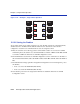
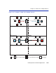
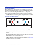
Figure 12-13 Switch Configured for VLANs
The switch will now classify each frame received as belonging to either the Red or Blue VLANs.
Traffic from one VLAN will not be forwarded to the members of the other VLAN, and all frames
transmitted by the switch will be normal, untagged Ethernet frames.
12.12.2Frame Handling
This section describes the operations of the switch when two frames are received. The first frame
is a broadcast sent by station R1.
1. Station R1 transmits the broadcast frame. The switch receives this frame on Port 1. As the frame
is received, the switch classifies it. The frame is untagged, so the switch classifies it as belonging
to the VLAN that Port 1 is assigned to, the Red VLAN.
2. At the same time, the switch adds the source MAC address of the frame and the VLAN
associated with port 1 to its Source Address Table in FID 2. In this fashion it learns that station
R1 is located out Port 1.
3. Once the frame is classified, its destination MAC address is examined. The switch discovers that
the frame is a broadcast, and treats it as it would any other unknown destination MAC address.
The switch forwards the frame out all ports in the Red VLAN’s Forwarding List except for the
one that received the frame. In this case, the frame is sent to Ports 2 and 3.
The second frame is a unicast, where station R2 responds to station R1’s broadcast.
4. Station R2, having received and recognized the broadcast from R1, transmits a unicast frame as
a response. The switch receives this frame on Port 2. The switch classifies this new untagged
frame as belonging to the Red VLAN.
5. The switch adds the source MAC address and VLAN for station R2 to its Source Address Table
in FID 2, and checks the Source Address Table for the destination MAC address given in the
3 6
2
4
5
B2
B1
B3
R1
R2
R2
802.1Q Switch
VLAN ID 002
VLAN ID 003VLAN ID 002
VLAN ID 003VLAN ID 002
VLAN ID 003
1
30691_68