
Owner manual


Example 3, 1D Trunk Connection to 802.1Q VLAN Network
12-36 VLAN Operation and Network Applications
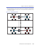
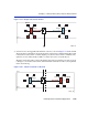
4. When Switch 1 receives the tagged broadcast frame, it also examines the tag and classifies the
frame as belonging to the Red VLAN. This broadcast frame is then sent to all ports eligible to
receive Red VLAN frames. In this case only the 1D trunk, Port 3, is eligible, as it is considered
a member of all VLANs for forwarding purposes. The VLAN Tag is stripped from the frame and
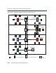
the frame is transmitted out Port 3 as shown in Figure 12-21. The Source Address Table, FID 1
for Switch 1 is updated to contain User B.
Figure 12-21 Switch 1 Forwards to 1D Trunk
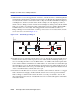
5. The Mail Server receives the broadcast frame and recognizes it. The Mail Server responds with
a unicast frame to User B. This frame crosses the 1D Trunk and is received by Switch 1. In this
example, Switch 1 classifies the unicast frame as belonging to the Default VLAN (the only
membership for the 1D Trunk port in this example).
Switch 1 checks the Filtering Database for the MAC address of User B. User B’s MAC address
is located, and Port 2 is identified as User B’s location. The frame is then checked for eligibility
and frame format for Port 2. Since Port 2 is a 1Q Trunk port, it is eligible to transmit frames for
all VLANs. The frame is tagged and transmitted out Port 2.
The switch also recognizes the MAC address of User B in its Source Address Table, FID 1, and
updates that table to contain the MAC address and port combination of the Mail Server.
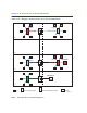
6. This tagged unicast frame is received by Switch 2. The frame is already tagged as belonging to
the Default VLAN, so no classification needs to be done. The switch recognizes User B’s MAC
address in its Source Address Table, FID 1, and updates that table to contain the Mail Server’s
MAC address and port combination.
Floor 1
Floor 2
1
1
2
3
4
Mail Server
Green VLAN
Green VLAN
Green, Inc.
2263_20