Enterasys® D-Series Ethernet Switches CLI Reference Firmware Version 1.00.01.
Notice Enterasys Networks reserves the right to make changes in specifications and other information contained in this document and its web site without prior notice. The reader should in all cases consult Enterasys Networks to determine whether any such changes have been made. The hardware, firmware, or software described in this document is subject to change without notice.
ENTERASYS NETWORKS, INC. FIRMWARE LICENSE AGREEMENT BEFORE OPENING OR UTILIZING THE ENCLOSED PRODUCT, CAREFULLY READ THIS LICENSE AGREEMENT. This document is an agreement (“Agreement”) between the end user (“You”) and Enterasys Networks, Inc.
If the Program is exported from the United States pursuant to the License Exception TSR under the U.S.
10. ENFORCEMENT. You acknowledge and agree that any breach of Sections 2, 4, or 9 of this Agreement by You may cause Enterasys irreparable damage for which recovery of money damages would be inadequate, and that Enterasys may be entitled to seek timely injunctive relief to protect Enterasys’ rights under this Agreement in addition to any and all remedies available at law. 11. ASSIGNMENT.
Contents About This Guide Using This Guide ............................................................................................................................................. xxi Structure of This Guide .................................................................................................................................... xxi Related Documents ........................................................................................................................................
set prompt......................................................................................................................................... 2-20 show banner motd ............................................................................................................................ 2-21 set banner motd................................................................................................................................ 2-21 clear banner motd..............................................
clear config ....................................................................................................................................... 2-46 Using and Configuring WebView .................................................................................................................. 2-47 Purpose .................................................................................................................................................. 2-47 Commands .......................................
show lldp port local-info .................................................................................................................... 5-18 show lldp port remote-info ................................................................................................................ 5-20 set lldp tx-interval.............................................................................................................................. 5-22 set lldp hold-multiplier ..........................................
Setting Flow Control ..................................................................................................................................... 6-19 Purpose .................................................................................................................................................. 6-19 Commands ............................................................................................................................................. 6-19 show flowcontrol ...................
set port protected name.................................................................................................................... 6-52 show port protected name ................................................................................................................ 6-52 clear port protected name................................................................................................................. 6-53 Chapter 7: SNMP Configuration SNMP Configuration Summary ......................
Purpose .................................................................................................................................................. 7-28 Commands ............................................................................................................................................. 7-29 show newaddrtrap ............................................................................................................................ 7-29 set newaddrtrap..................................
show spantree tctrapsuppress.......................................................................................................... 8-23 set spantree tctrapsuppress ............................................................................................................. 8-23 clear spantree tctrapsuppress .......................................................................................................... 8-24 set spantree protomigration ...........................................................
show spantree nonforwardingreason ............................................................................................... 8-53 Chapter 9: 802.1Q VLAN Configuration VLAN Configuration Summary ....................................................................................................................... 9-1 Port String Syntax Used in the CLI .......................................................................................................... 9-1 Creating a Secure Management VLAN ........
Command ............................................................................................................................................... 10-2 set diffserv adminmode .................................................................................................................... 10-2 Creating Diffserv Classes and Matching Conditions .................................................................................... 10-3 Purpose ..............................................................
set cos state ................................................................................................................................... 11-19 show cos state................................................................................................................................ 11-20 clear cos state ................................................................................................................................ 11-20 set cos settings............................................
set igmpsnooping interfacemode...................................................................................................... 13-3 set igmpsnooping groupmembershipinterval .................................................................................... 13-4 set igmpsnooping maxresponse ....................................................................................................... 13-5 set igmpsnooping mcrtrexpiretime.........................................................................
Configuring Simple Network Time Protocol (SNTP) ................................................................................... 14-26 Purpose ................................................................................................................................................ 14-26 Commands ........................................................................................................................................... 14-26 show sntp ..................................................
show rmon filter .............................................................................................................................. 15-19 set rmon filter .................................................................................................................................. 15-20 clear rmon filter ............................................................................................................................... 15-21 Packet Capture Commands .................................
clear dhcp pool dns-server ............................................................................................................. 16-23 set dhcp pool domain-name ........................................................................................................... 16-24 clear dhcp pool domain-name ........................................................................................................ 16-24 set dhcp pool netbios-name-server ........................................................
Configuring Multiple Authentication Methods ............................................................................................. 17-33 About Multiple Authentication Types .................................................................................................... 17-33 Configuring Multi-User Authentication (User + IP phone) .................................................................... 17-33 Commands .....................................................................................
set pwa ipaddress........................................................................................................................... 17-67 set pwa protocol ............................................................................................................................. 17-67 set pwa guestname ........................................................................................................................ 17-68 clear pwa guestname ...................................................
7-18 7-19 7-20 7-21 7-22 8-23 9-24 9-25 9-26 10-27 11-28 11-29 11-30 12-31 14-32 14-33 14-34 14-35 14-36 14-37 14-38 15-39 15-40 15-41 17-42 17-43 17-44 17-45 17-46 17-47 17-48 17-49 xxii show snmp view Output Details ....................................................................................................... 7-20 show snmp targetparams Output Details ......................................................................................... 7-23 show snmp targetaddr Output Details ..............
About This Guide Welcome to the Enterasys Networks D‐Series CLI Reference. This manual explains how to access the device’s Command Line Interface (CLI) and how to use it to configure Enterasys® D‐Series switch devices. Important Notice Depending on the firmware version used in your switching device, some features described in this document may not be supported. Refer to the Release Notes shipped with your device to determine which features are supported.
Related Documents Chapter 7, SNMP Configuration, describes how to configure SNMP users and user groups, access rights, target addresses, and notification parameters. Chapter 8, Spanning Tree Configuration, describes how to review and set Spanning Tree bridge parameters for the device, including bridge priority, hello time, maximum aging time and forward delay; and how to review and set Spanning Tree port parameters, including port priority and path costs.
Conventions Used in This Guide Conventions Used in This Guide The following conventions are used in the text of this document: Convention Description Bold font Indicates mandatory keywords, parameters or keyboard keys. italic font Indicates complete document titles. Courier font Used for examples of information displayed on the screen. Courier font in italics Indicates a user-supplied value, either required or optional. [] Square brackets indicate an optional value.
Getting Help Before calling Enterasys Networks, have the following information ready: xxiv • Your Enterasys Networks service contract number • A description of the failure • A description of any action(s) already taken to resolve the problem (for example, changing mode switches or rebooting the unit) • The serial and revision numbers of all involved Enterasys Networks products in the network • A description of your network environment (for example, layout, cable type) • Network load and frame
1 Introduction This chapter provides an overview of the D‐Series’s unique features and functionality, an overview of the tasks that may be accomplished using the CLI interface, an overview of ways to manage the switch, factory default settings, and information about how to use the Command Line Interface to configure the switch. For information about... Refer to page...
Factory Default Settings • Remotely using WebView™, Enterasys Networks’ embedded web server application. The Installation Guide for your D‐Series device provides setup instructions for connecting a terminal or modem to the switch. Factory Default Settings The following tables list factory default settings available on the D‐Series switch. Table 1-1 Default Settings for Basic Switch Operation Feature Default Setting Switch Mode Defaults CDP discovery protocol Auto enabled on all ports.
Factory Default Settings Table 1-1 Default Settings for Basic Switch Operation (Continued) Feature Default Setting Link aggregation flow regeneration Disabled. Link aggregation system priority Set to 32768 for all ports. Link aggregation outport algorithm Set to DIP-SIP. Lockout Set to disable Read-Write and Read-Only users, and to lockout the default admin (Super User) account for 15 minutes, after 3 failed login attempts. Logging Syslog port set to UDP port number 514.
Factory Default Settings Table 1-1 1-4 Introduction Default Settings for Basic Switch Operation (Continued) Feature Default Setting Spanning Tree edge port administrative status Edge port administrative status begins with the value set to false initially after the device is powered up. If a Spanning Tree BDPU is not received on the port within a few seconds, the status setting changes to true. Spanning Tree edge port delay Enabled. Spanning Tree forward delay Set to 15 seconds.
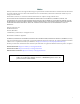
Using the Command Line Interface Using the Command Line Interface Starting a CLI Session Connecting Using the Console Port Connect a terminal to the local console port as described in your D‐Series Installation Guide. The startup screen, Figure 1‐1, will display on the terminal.
Using the Command Line Interface Refer to the instructions included with the Telnet application for information about establishing a Telnet session. Logging In By default, the D‐Series switch is configured with three user login accounts—ro for Read‐Only access, rw for Read‐Write access, and admin for super‐user access to all modifiable parameters. The default password is set to a blank string. For information on changing these default settings, refer to “Setting User Accounts and Passwords” on page 3‐2.
Using the Command Line Interface Figure 1-2 Sample CLI Defaults Description Syntax show port status [port-string] Defaults If port‐string is not specified, status information for all ports will be displayed. CLI Command Modes Each command description in this guide includes a section entitled “Mode” which states whether the command is executable in Admin (Super User), Read‐Write, or Read‐Only mode. Users with Read‐Only access will only be permitted to view Read‐Only (show) commands.
Using the Command Line Interface Displaying Scrolling Screens If the CLI screen length has been set using the set length command as described on page 3‐26, CLI output requiring more than one screen will display --More-- to indicate continuing screens. To display additional screen output: • Press any key other than ENTER to advance the output one screen at a time. • Press ENTER to advance the output one line at a time.
Using the Command Line Interface Basic Line Editing Commands The CLI supports EMACs‐like line editing commands. Table 1‐2 lists some commonly used commands. Table 1-2 Basic Line Editing Commands Key Sequence Command Ctrl+A Move cursor to beginning of line. Ctrl+B Move cursor back one character. Ctrl+D Delete a character. Ctrl+E Move cursor to end of line. Ctrl+F Move cursor forward one character. Ctrl+H Delete character to left of cursor. Ctrl+I or TAB Complete word.
Using the Command Line Interface 1-10 Introduction
2 Basic Configuration At startup, the D‐Series switch is configured with many defaults and standard features. This chapter describes how to customize basic system settings to adapt to your work environment. For information about... Refer to page...
Setting User Accounts and Passwords Table 2-2 Optional CLI Setup Commands Refer to page... Task CLI commands Save the active configuration. save config 2-36 Enable or disable SSH. set ssh enable | disable 17-74 Enable or disable Telnet. set telnet {enable | disable} [inbound | outbound | all] 2-33 Enable or disable HTTP management (WebView). set webview {enable | disable} 2-48 Enable or disable SNMP port link traps.
show system login show system login Use this command to display user login account information. Syntax show system login Parameters None. Defaults None. Mode Switch command, super user. Example This example shows how to display login account information.
set system login set system login Use this command to create a new user login account, or to disable or enable an existing account. The D‐Series switch supports up to 16 user accounts, including the admin account, which cannot be deleted. Syntax set system login username {super-user | read-write | read-only} {enable | disable} Parameters username Specifies a login name for a new or existing user.
set password Mode Switch command, super user. Example This example shows how to remove the “netops” user account: D2(su)->clear system login netops set password Use this command to change system default passwords or to set a new login password on the CLI. Syntax set password [username] Parameters username (Only available to users with super‐user access.) Specifies a system default or a user‐configured login account name.
set system password length Please enter new password: ******** Please re-enter new password: ******** Password changed. D2(su)-> set system password length Use this command to set the minimum user login password length. Syntax set system password length characters Parameters characters Specifies the minimum number of characters for a user account password. Valid values are 0 to 40. Defaults None. Mode Switch command, super user.
set system password history Example This example shows how to set the system password age time to 45 days: D2(su)->set system password aging 45 set system password history Use this command to set the number of previously used user login passwords that will be checked for password duplication. This prevents duplicate passwords from being entered into the system with the set password command.
set system lockout Example This example shows how to display user lockout settings. In this case, switch defaults have not been changed: D2(su)->show system lockout Lockout attempts: 3 Lockout time: 15 minutes. Table 2‐3 provides an explanation of the command output. These settings are configured with the set system lockout command (“set system lockout” on page 2‐8). Table 2-3 show system lockout Output Details Output Field What It Displays...
Setting Basic Switch Properties Setting Basic Switch Properties Purpose To display and set the system IP address and other basic system (switch) properties. Commands For information about... Refer to page...
show ip address For information about... Refer to page... show console 2-27 set console baud 2-28 show ip address Use this command to display the system IP address and subnet mask. Syntax show ip address Parameters None. Defaults None. Mode Switch command, read‐only. Example This example shows how to display the system IP address and subnet mask: D2(su)->show ip address Name ---------------host Address ---------------10.42.13.20 Mask ---------------255.255.0.
clear ip address Mode Switch command, read‐write. Usage Paramters must be entered in the order shown (host IP, then mask, then gateway) for the command to be accepted. Example This example shows how to set the system IP address to 10.1.10.1 with a mask of 255.255.128.0: D2(su)->set ip address 10.1.10.1 mask 255.255.128.0 clear ip address Use this command to clear the system IP address. Syntax clear ip address Parameters None. Defaults None. Mode Switch command, read‐write.
set ip protocol Mode Switch command, read‐only. Example This example shows how to display the method used to acquire a network IP address: D2(su)->show ip protocol System IP address acquisition method: dhcp set ip protocol Use this command to specify the protocol used to acquire a network IP address for switch management. Syntax set ip protocol {bootp | dhcp | none} Parameters bootp Selects BOOTP as the protocol to use to acquire the system IP address.
show system Mode Switch command, read‐only.
show system hardware show system hardware Use this command to display the system’s hardware configuration. Syntax show system hardware Parameters None. Defaults None. Mode Switch command, read‐only. Example This example shows how to display the system’s hardware configuration. Please note that the information you see displayed may differ from this example.
show system enhancedbuffermode Mode Switch command, read‐only.
set system enhancedbuffermode Mode Switch command, read‐write. Example This example shows how to display enhanced buffer mode status: D2(su)->show system enhancedbuffermode enable Optimized system buffer distribution Disable set system enhancedbuffermode Use this command to enable or disable enhanced buffer mode, which optimizes buffer distribution for non‐stacking single CoS queue operation. Executing this command will reset the switch, so the system prompts you to confirm whether you want to proceed.
set time Mode Switch command, read‐only. Example This example shows how to display the current time. The output shows the day of the week, month, day, and the time of day in hours, minutes, and seconds and the year: D2(su)->show time THU SEP 05 09:21:57 2002 set time Use this command to change the time of day on the system clock.
set summertime Mode Switch command, read‐only. Example This example shows how to display daylight savings time settings: D2(su)->show summertime Summertime is disabled and set to '' Start : SUN APR 04 02:00:00 2004 End : SUN OCT 31 02:00:00 2004 Offset: 60 minutes (1 hours 0 minutes) Recurring: yes, starting at 2:00 of the first Sunday of April and ending at 2:00 of the last Sunday of October set summertime Use this command to enable or disable the daylight savings time function.
set summertime recurring start_year Specifies the year to start daylight savings time. start_hr_min Specifies the time of day to start daylight savings time. Format is hh:mm. end_month Specifies the month of the year to end daylight savings time. end_date Specifies the day of the month to end daylight savings time. end_year Specifies the year to end daylight savings time. end_hr_min Specifies the time of day to end daylight savings time. Format is hh:mm.
clear summertime Defaults If an offset is not specified, none will be applied. Mode Switch command, read‐write. Example This example shows how set daylight savings time to recur starting on the first Sunday of April at 2 a.m. and ending the last Sunday of October at 2 a.m. with an offset time of one hour: D2(su)->set summertime recurring first Sunday April 02:00 last Sunday October 02:00 60 clear summertime Use this command to clear the daylight savings time configuration.
show banner motd Defaults None. Mode Switch command, read‐write. Example This example shows how to set the command prompt to Switch 1: D2(su)->set prompt “Switch 1” Switch 1(su)-> show banner motd Use this command to show the banner message of the day that will display at session login. Syntax show banner motd Parameters None. Defaults None. Mode Switch command, read‐only.
clear banner motd Parameters message Specifies a message of the day. This is a text string that needs to be in double quotes if any spaces are used. Use a \n for a new line and \t for a tab (eight spaces). Defaults None. Mode Switch command, read‐write.
set system name Parameters None. Defaults None. Mode Switch command, read‐only. Example This example shows how to display version information. Please note that you may see different information displayed, depending on the type of hardware. D2(su)->show version Copyright (c) 2008 by Enterasys Networks, Inc. Model -------------D2G124-12P Serial # ----------------001188021035 Versions ------------------Hw:BCM5665 REV 17 Bp:01.00.29 Fw:1.0.xx BuFw:03.01.
set system location Defaults If string is not specified, the system name will be cleared. Mode Switch command, read‐write. Example This example shows how to set the system name to Information Systems: D2(su)->set system name “Information Systems” set system location Use this command to identify the location of the system. Syntax set system location [string] Parameters string (Optional) Specifies a text string that indicates where the system is located.
set width Parameters string (Optional) Specifies a text string that contains the name of the person to contact for system administration. Note: A contact string containing a space in the text must be enclosed in quotes as shown in the example below. Defaults If string is not specified, the contact name will be cleared. Mode Switch command, read‐write.
set length set length Use this command to set the number of lines the CLI will display. This command is persistent (written to NV‐RAM). Syntax set length screenlength Parameters screenlength Sets the number of lines in the CLI display. Valid values are 0, which disables the scrolling screen feature described in “Displaying Scrolling Screens” on page 1‐8, and from 5 to 512. Defaults None. Mode Switch command, read‐write.
set logout set logout Use this command to set the time (in minutes) an idle console or Telnet CLI session will remain connected before timing out. Syntax set logout timeout Parameters timeout Sets the number of minutes the system will remain idle before timing out. Defaults None. Mode Switch command, read‐write. Example This example shows how to set the system timeout to 10 minutes: D2(su)->set logout 10 show console Use this command to display console settings.
set console baud -----9600 ------Disable ---8 ---------1 -----none set console baud Use this command to set the console port baud rate. Syntax set console baud rate Parameters rate Sets the console baud rate. Valid values are: 300, 600, 1200, 2400, 4800, 5760, 9600, 14400, 19200, 38400, and 115200. Defaults None. Mode Switch command, read‐write.
Downloading a Firmware Image Downloading from a TFTP Server To perform a TFTP download, proceed as follows: 1. If you have not already done so, set the switch’s IP address using the set ip address command as detailed in “set ip address” on page 2‐10. 2. Download a new image file using the copy command as detailed in “copy” on page 2‐40. Downloading via the Serial Port To download switch firmware via the serial (console) port, proceed as follows: 1. With the console port connected, power up the switch.
Downloading a Firmware Image 7 - 57600 8 - 115200 0 - no change 4. Type 8 to set the switch baud rate to 115200. The following message displays: Setting baud rate to 115200, you must change your terminal baud rate. 5. Set the terminal baud rate to 115200 and press ENTER. 6. From the boot menu options screen, type 4 to load new operational code using XMODEM.
Reviewing and Selecting a Boot Firmware Image 2. Load your previous version of code on the device, as described in “Downloading a Firmware Image” (page 2‐28). 3. Set this older version of code to be the boot code, as described in “Reviewing and Selecting a Boot Firmware Image” (page 2‐31). 4. Reload the saved configuration onto the device as described in“configure” (page 2‐39). Reviewing and Selecting a Boot Firmware Image Purpose To display and set the image file the switch loads at startup.
set boot system set boot system Use this command to set the firmware image the switch loads at startup. Syntax set boot system filename Parameters filename Specifies the name of the firmware image file. Defaults None. Mode Switch command, read‐write. Example This example shows how to set the boot firmware image file to “newimage”: D2(su)->set boot system newimage Starting and Configuring Telnet Purpose To enable or disable Telnet, and to start a Telnet session to a remote host.
set telnet Defaults None. Mode Switch command, read‐only. Example This example shows how to display Telnet status: D2(su)->show telnet Telnet inbound is currently: ENABLED Telnet outbound is currently: ENABLED set telnet Use this command to enable or disable Telnet on the switch. Syntax set telnet {enable | disable} [inbound | outbound | all] Parameters enable | disable Enables or disables Telnet services.
Managing Switch Configuration and Files Parameters host Specifies the name or IP address of the remote host. port (Optional) Specifies the server port number. Defaults If not specified, the default port number 23 will be used. Mode Switch command, read‐write. Example This example shows how to start a Telnet session to a host at 10.21.42.13: D2(su)->telnet 10.21.42.
show snmp persistmode Commands For information about... Refer to page... show snmp persistmode 2-35 set snmp persistmode 2-36 save config 2-36 dir 2-37 show file 2-38 show config 2-38 configure 2-39 copy 2-40 delete 2-41 show tftp settings 2-41 set tftp timeout 2-42 clear tftp timeout 2-42 set tftp retry 2-43 clear tftp retry 2-43 show snmp persistmode Use this command to display the configuration persistence mode setting. Syntax show snmp persistmode Parameters None.
set snmp persistmode Example This example shows how to display the configuration persistence mode setting. In this case, persistence mode is set to “manual”, which means configuration changes are not being automatically saved. D2(su)->show snmp persistmode persistmode is manual set snmp persistmode Use this command to set the configuration persistence mode, which determines whether user‐ defined configuration changes are saved automatically, or require issuing the save config command.
dir Mode Switch command, read‐write. Example This example shows how to save the running configuration: D2(su)->save config dir Use this command to list configuration and image files stored in the file system. Syntax dir [filename] Parameters filename (Optional) Specifies the file name or directory to list. Defaults If filename is not specified, all files in the system will be displayed. Mode Switch command, read‐only.
show file current.log 90129 show file Use this command to display the contents of a file. Syntax show file filename Parameters filename Specifies the name of the file to display. Defaults None. Mode Switch command, read‐only. Example This example shows how to display a text file named “mypolicy” in the configs/ directory. Note that only a portion of the file is shown in this example.
configure Parameters all (Optional) Displays default and non‐default configuration settings. facility (Optional) Specifies the exact name of one facility for which to show configuration. For example, enter “router” to show only router configuration. outfile (Optional) Specifies that the current configuration will be written to a text file in the configs/ directory. configs/filename Specifies a filename in the configs/ directory to display.
copy Parameters filename Specifies the path and file name of the configuration file to execute. append (Optional) Appends the configuration file contents to the current configuration. This is equivalent to typing the contents of the config file directly into the CLI and can be used, for example, to make incremental adjustments to the current configuration.
delete delete Use this command to remove an image or a CLI configuration file from the switch. Syntax delete filename Parameters filename Specifies the local path name to the file. Valid directories are /images and /configs.44. Defaults None. Mode Switch command, read‐write. Usage Use the dir command (page 2‐37) to display current image and configuration file names. Example This example shows how to delete the “Jan1_2004.cfg” configuration file: D2(su)->delete configs/Jan1_2004.
set tftp timeout Example This example shows the output of this command. D2(ro)->show tftp settings TFTP packet timeout (seconds): 2 TFTP max retry: 5 set tftp timeout Use this command to configure how long TFTP will wait for a reply of either an acknowledgement packet or a data packet during a data transfer. Syntax set tftp timeout seconds Parameters seconds Specifies the number of seconds to wait for a reply. The valid range is from 1 to 30 seconds. Default value is 2 seconds. Defaults None.
set tftp retry Example This example shows how to clear the timeout value to the default of 2 seconds. D2(rw)-> clear tftp timeout set tftp retry Use this command to configure how many times TFTP will resend a packet, either an acknowledgement packet or a data packet. Syntax set tftp retry retry Parameters retry Specifies the number of times a packet will be resent. The valid range is from 1 to 1000. Default value is 5 retries. Defaults None. Mode Switch command, read‐write.
Clearing and Closing the CLI Clearing and Closing the CLI Purpose To clear the CLI screen or to close your CLI session. Commands For information about... cls 2-44 exit 2-44 cls (clear screen) Use this command to clear the screen for the current CLI session. Syntax cls Parameters None. Defaults None. Mode Switch command, read‐only. Example This example shows how to clear the CLI screen: D2(su)->cls exit Use either of these commands to leave a CLI session. Syntax exit Parameters None.
Resetting the Switch Mode Switch command, read‐only. Usage By default, switch timeout occurs after 15 minutes of user inactivity, automatically closing your CLI session. Use the set logout command (page 2‐27) to change this default. Example This example shows how to exit a CLI session: D2(su)->exit Resetting the Switch Purpose To reset one or more switches, and to clear the user‐defined configuration parameters. Commands For information about... Refer to page...
clear config Do you want to continue (y/n) [n]? clear config Use this command to clear the user‐defined configuration parameters. Syntax clear config [all] Parameters all (Optional) Clears user‐defined configuration parameters (and stack unit numbers and priorities, if applicable). Defaults If all is not specified, stacking configuration parameters will not be cleared. Mode Switch command, read‐write.
Using and Configuring WebView Using and Configuring WebView Purpose By default, WebView (The Enterasys Networks embedded web server for switch configuration and management tasks) is enabled on TCP port number 80 on the D‐Series switch. You can verify WebView status, and enable or disable WebView using the commands described in this section. WebView can also be securely used over SSL port 443, if SSL is enabled on the switch. By default, SSL is disabled.
set webview set webview Use this command to enable or disable WebView on the switch. Syntax set webview {enable | disable} Parameters enable | disable Enable or disable WebView on the switch. Defaults None. Mode Switch command, read‐write. Usage It is good practice for security reasons to disable HTTP access on the switch when finished configuring with WebView, and then to only enable WebView on the switch when changes need to be made.
set ssl set ssl Use this command to enable or disable the use of WebView over SSL port 443. By default, SSL is disabled on the switch. This command can also be used to reinitialize the hostkey that is used for encryption. Syntax set ssl {enabled | disabled | reinitialize | hostkey reinitialize} Parameters enabled | disabled Enable or disable the ability to use WebView over SSL. reinitialize Stops and then restarts the SSL process.
set ssl 2-50 Basic Configuration
3 Activating Licensed Features In order to enable the D2 advanced features, such as Policy, you must purchase a license. If you have purchased a license, you can proceed to activate your license as described in this section. If you wish to obtain a permanent or evaluation license, contact the Enterasys Networks Sales Department. Clearing, Showing, and Moving Licenses Licenses can be displayed, applied, and cleared only with the license commands described in this chapter.
show license Usage When you execute the set license command, you will be prompted to accept the license agreement. If you do not accept the license agreement, the licensed feature will not be enabled. Example This example shows how to activate a license on a D‐Series switch. D2(rw)->set license D2Policy Terms of this license may be found at http://www.enterasys.com/support/fla.
clear license Parameters featureID feature The name of the feature being cleared. Defaults None. Mode Switch command, read‐write.
clear license 3-4 Activating Licensed Features
4 Configuring System Power and PoE Important Notice Some commands in this section apply only to PoE-equipped D-Series devices. Consult the Installation Guide shipped with your product to determine if it is PoE-equipped. The commands in this chapter allow you to review and set system power and PoE parameters, including the power available to the system, the usage threshold for each module, whether or not SNMP trap messages will be sent when power status changes, and per‐port PoE settings.
set inlinepower threshold Example This example shows how to display system power properties: D2(su)->show inlinepower Detection Mode : auto Unit ---1 Status -----auto Power(W) -------480 Consumption(W) -------------0.00 Usage(%) -------0.00 Threshold(%) -----------80 Trap ---enable set inlinepower threshold Use this command to set the power usage thresholdon a specified unit or module.
show port inlinepower Example This example shows how to enable inline power trap messaging on module 1: D2(su)->set inlinepower trap enable 1 show port inlinepower Use this command to display all ports supporting PoE. Syntax show port inlinepower [port-string] Parameters port‐string (Optional) Displays information for specific PoE port(s). Defaults If not specified, information for all PoE ports will be displayed. Mode Switch command, read‐only.
set port inlinepower Mode Switch command, read‐write. Example This example shows how to enable PoE on port fe.3.1 with critical priority: D2(su)->set port inlinepower fe.3.
5 Discovery Protocol Configuration This chapter describes how to configure discovery protocols. For information about... Refer to page... Configuring CDP 5-1 Configuring Cisco Discovery Protocol 5-7 Configuring Link Layer Discovery Protocol and LLDP-MED 5-13 Configuring CDP Purpose To review and configure the Enterasys CDP discovery protocol. This protocol is used to discover network topology.
show cdp show cdp Use this command to display the status of the CDP discovery protocol and message interval on one or more ports. Syntax show cdp [port-string] Parameters port‐string (Optional) Displays CDP status for a specific port. For a detailed description of possible port‐string values, refer to “Port String Syntax Used in the CLI” on page 6‐1. Defaults If port‐string is not specified, all CDP information will be displayed. Mode Switch command, read‐only.
set cdp state Table 5-1 show cdp Output Details (Continued) Output Field What It Displays... CDP Authentication Code Authentication code for CDP discovery protocol. The default of 00-00-00-00-00-0000-00 can be reset using the set cdp auth command. For details, refer to “set cdp auth” on page 5-4. CDP Transmit Frequency Frequency (in seconds) at which CDP messages can be transmitted. The default of 60 seconds can be reset with the set cdp interval command.
set cdp auth set cdp auth Use this command to set a global CDP authentication code. Syntax set cdp auth auth-code Parameters auth‐code Specifies an authentication code for the CDP protocol. This can be up to 16 hexadecimal values separated by commas. Defaults None. Mode Switch command, read‐write. Usage The authentication code value determines a switch’s CDP domain. If two or more switches have the same CDP authentication code, they will be entered into each other’s CDP neighbor tables.
set cdp hold-time Example This example shows how to set the CDP interval frequency to 15 seconds: D2(su)->set cdp interval 15 set cdp hold-time Use this command to set the hold time value for CDP discovery protocol configuration messages. Syntax set cdp hold-time hold-time Parameters hold‐time Specifies the hold time value for CDP messages in seconds.Valid values are from 15 to 600. Defaults None. Mode Switch command, read‐write.
show neighbors Mode Switch command, read‐write. Example This example shows how to reset the CDP state to auto‐enabled: D2(su)->clear cdp state show neighbors This command displays Neighbor Discovery information for either the CDP or Cisco DP protocols. Syntax show neighbors [port-string] Parameters port‐string (Optional) Specifies the port or ports for which to display Neighbor Discovery information. Defaults If no port is specified, all Neighbor Discovery information is displayed.
Configuring Cisco Discovery Protocol Configuring Cisco Discovery Protocol Purpose To review and configure the Cisco discovery protocol. Discovery protocols are used to discover network topology. When enabled, they allow Cisco devices to send periodic PDUs about themselves to neighboring devices. Specifically, this feature enables recognizing PDUs from Cisco phones. A table of information about detected phones is kept by the switch and can be queried by the network administrator.
show ciscodp port info Device ID : 001188554A60 Last Change : WED NOV 08 13:19:56 2006 Table 5‐2 provides an explanation of the command output. Table 5-2 show ciscodp Output Details Output Field What It Displays... CiscoDP Whether Cisco DP is globally enabled or disabled. Auto indicates that Cisco DP will be globally enabled only if Cisco DP PDUs are received. Default setting of auto-enabled can be reset with the set ciscodp status command.
set ciscodp status Table 5-3 show ciscodp port info Output Details Output Field What It Displays... Port Port designation. For a detailed description of possible port-string values, refer to “Port String Syntax Used in the CLI” on page 6-1. State Whether Cisco DP is enabled, disabled or auto-enabled on the port. Default state of enabled can be changed using the set ciscodp port command. vvid Whether a voice VLAN ID has been set on this port.
set ciscodp holdtime Parameters seconds Specifies the number of seconds between Cisco DP PDU transmissions. Valid values are from 5 to 254 seconds. Defaults None. Mode Switch command, read‐write. Example This example shows how to set the Cisco DP timer to 120 seconds. D2(su)->set ciscodp timer 120 set ciscodp holdtime Use this command to set the time to live (TTL) for Cisco discovery protocol PDUs.
set ciscodp port Parameters status Sets the CiscoDP port operational status. disable Does not transmit or process CiscoDP PDUs. enable Transmits and processes CiscoDP PDUs. vvid Sets the port voice VLAN for CiscoDP PDU transmission. vlan‐id Specifies the VLAN ID, range 1‐4094. none No voice VLAN will be used in CiscoDP PDUs. This is the default. dot1p Instructs attached phone to send 802.1p tagged frames. untagged Instructs attached phone to send untagged frames.
clear ciscodp • If the switch port is configured to a Cisco DP trust state of untrusted (trusted no), this setting is communicated to the Cisco IP phone instructing it to overwrite the 802.1p tag of traffic transmitted by the device connected to it to 0, by default, or to the value specified by the cos parameter of this command. • There is a one‐to‐one correlation between the value set with the cos parameter and the 802.1p value assigned to ingressed traffic by the Cisco IP phone.
Configuring Link Layer Discovery Protocol and LLDP-MED Examples This example shows how to clear all the Cisco DP parameters back to the default settings. D2(rw)->clear ciscodp This example shows how to clear the Cisco DP status on port fe.1.5. D2(rw)->clear ciscodp port status fe.1.
Configuring Link Layer Discovery Protocol and LLDP-MED For information about... Refer to page...
show lldp show lldp Use this command to display LLDP configuration information. Syntax show lldp Parameters None. Defaults None. Mode Switch command, read‐only. Example This example shows how to display LLDP configuration information. D2(ro)->show lldp Message Tx Interval Message Tx Hold Multiplier Notification Tx Interval MED Fast Start Count : : : : Tx-Enabled Ports Rx-Enabled Ports : ge.1.1-60; ge.2.1-24; ge.3.1-30; ge.4.1-12; : ge.1.1-60; ge.2.1-24; ge.3.1-30; ge.4.
show lldp port trap Example This example shows how to display LLDP port status information for all ports. D2(ro)->show lldp port status Tx-Enabled Ports : ge.1.1-60; ge.2.1-24; ge.3.1-30; ge.4.1-12 Rx-Enabled Ports : ge.1.1-60; ge.2.1-24; ge.3.1-30; ge.4.1-12 show lldp port trap Use this command to display the ports that are enabled to send an LLDP notification when a remote system change has been detected or an LLDP‐MED notification when a change in the topology has been sensed.
show lldp port location-info Parameters port‐string (Optional) Displays information about TLV configuration for one or a range of ports. Defaults If port‐string is not specified, TLV configuration information will be displayed for all ports. Mode Switch command, read‐only. Example This example shows how to display transmit TLV information for three ports. D2(ro)->show lldp port tx-tlv ge.1.
show lldp port local-info Ports -------ge.1.1 ge.1.2 ge.1.3 Type ------------ELIN ELIN ELIN Location ------------------------1234567890 1234567890 1234567890 show lldp port local-info Use this command to display the local system information stored for one or more ports. You can use this information to detect misconfigurations or incompatibilities between the local port and the attached endpoint device (remote port).
show lldp port local-info PoE PoE PoE PoE PoE PoE PoE Device Power Source MDI Supported/Enabled Pair Controllable/Used Power Class Power Limit (mW) Power Priority : : : : : : : PSE device primary yes/yes false/spare 2 15400 high Table 5‐4 describes the information displayed by the show lldp port local‐info command. Table 5-4 show lldp port local-info Output Details Output Field What it Displays... Local Port Identifies the port for which local system information is displayed.
show lldp port remote-info Table 5-4 show lldp port local-info Output Details (Continued) Output Field What it Displays... PoE Power Source LLDP-MED Extensions Extended Power via MDI TLV. Displayed only when a port has PoE capabilities. Value can be primary or backup, indicating whether the PSE is using its primary or backup power source. PoE MDI Supported/Enabled IEEE 802.3 Extensions Power via MDI TLV. Displayed only when a port has PoE capabilities.
show lldp port remote-info Example This example shows how to display the remote system information stored for port ge.3.1. The remote system information was received from an IP phone, which is an LLDP‐MED‐enabled device. Table 5‐5 describes the output fields that are unique to the remote system information displayed for a MED‐enabled device. D2(ro)->show lldp port remote-info ge.3.1 Local Port : ge.3.1 Remote Port Id : 00-09-6e-0e-14-3d --------------------Mgmt Addr : 0.0.0.0 Chassis ID : 0.0.0.
set lldp tx-interval set lldp tx-interval Use this command to set the time, in seconds, between successive LLDP frame transmissions initiated by changes in the LLDP local system information. Syntax set lldp tx-interval frequency Parameters frequency Specifies the number of seconds between transmissions of LLDP frames. Value can range from 5 to 32,768 seconds. The default is 30 seconds. Defaults None. Mode Switch command, read‐write. Example This example sets the transmit interval to 20 seconds.
set lldp trap-interval set lldp trap-interval Use this command to set the minimum interval between LLDP notifications sent by this device. LLDP notifications are sent when a remote system change has been detected. Syntax set lldp trap-interval frequency Parameters frequency Specifies the minimum time between LLDP trap transmissions, in seconds. The value can range from 5 to 3600 seconds. The default value is 5 seconds. Defaults None. Mode Switch command, read‐write.
set lldp port status Example This example sets the number of fast start LLDPDUs to be sent to 4. D2(rw)->set lldp med-fast-repeat 4 set lldp port status Use this command to enable or disable transmitting and processing received LLDPDUs on a port or range of ports. Syntax set lldp port status {tx-enable | rx-enable | both | disable} port-string Parameters tx‐enable Enables transmitting LLDPDUs on the specified ports.
set lldp port med-trap Defaults None. Mode Switch command, read‐write. Example This example enables transmitting LLDP traps on ports ge.1.1 through ge.1.6. D2(rw)->set lldp port trap enable ge.1.1-6 set lldp port med-trap Use this command to enable or disable sending an LLDP‐MED notification when a change in the topology has been sensed on the port (that is, a remote endpoint device has been attached or removed from the port).
set lldp port tx-tlv Parameters 5-26 all Adds all optional TLVs to transmitted LLDPDUs. port‐desc Port Description optional basic LLDP TLV. Value sent is ifDescr object defined in RFC 2863. sys‐name System Name optional basic LLDP TLV. Value sent is the administratively assigned name for the system. sys‐desc System Description optional basic LLDP TLV. Value sent is sysDescr object defined in RFC 3418. sys‐cap System Capabilities optional basic LLDP TLV.
clear lldp Defaults None. Mode Switch command, read‐write. Example This example configures the management address, MED capability, and MED location identification TLVs to be sent in LLDPDUs by port ge.1.1. D2(rw)->set lldp port tx-tlv mgmt-addr med-cap med-loc ge.1.1 clear lldp Use this command to return LLDP parameters to their default values.
clear lldp port trap Syntax clear lldp port status port-string Parameters port‐string Specifies the port or range of ports to be affected. Defaults None. Mode Switch command, read‐write. Example This example returns port ge.1.1 to the default state of enabled for both transmitting and processing received LLDPDUs. D2(rw)->clear lldp port status ge.1.1 clear lldp port trap Use this command to return the port LLDP trap setting to the default value of disabled.
clear lldp port tx-tlv Parameters port‐string Specifies the port or range of ports to be affected. Defaults None. Mode Switch command, read‐write. Example This example returns port ge.1.1 to the default LLDP‐MED trap state of disabled. D2(rw)->clear lldp port med-trap ge.1.1 clear lldp port tx-tlv Use this command to clear the optional LLDP and LLDP‐MED TLVs to be transmitted in LLDPDUs by the specified port or ports to the default value of disabled.
clear lldp port tx-tlv poe Disables the Power via MDI IEEE 802.3 Extensions TLV from being transmitted in LLDPDUs. Only valid for PoE‐enabled ports. link‐aggr Disables the Link Aggregation IEEE 802.3 Extensions TLV from being transmitted in LLDPDUs. max‐frame Disables the Maximum Frame Size IEEE 802.3 Extensions TLV from being transmitted in LLDPDUs. med‐cap Disables the LLDP‐MED Capabilities TLV from being transmitted in LLDPDUs.
6 Port Configuration This chapter describes the Port Configuration set of commands and how to use them. For information about... Refer to page...
Port Configuration Summary Port Slot/Unit Parameters Used in the CLI The “unit” parameter is often used interchangeably with “module” in the standalone switch CLI to indicate a module slot location. Examples Note: You can use a wildcard (*) to indicate all of an item. For example, fe.3.* would represent all 100Mbps Ethernet (fe) ports in slot 3, and ge.3 * would represent all 1-Gigabit Ethernet (ge) ports in slot 3.
Reviewing Port Status Example This example shows how to configure port ge.2.1 in the D2G124‐12 to operate with a 100BASE‐FX transceiver installed. First, the port status is shown as operating as a 1000BASE‐SX port. After the 1‐Gigabit transceiver is replaced with the a 100 Mbps transceiver, the port is configured appropriately and the new settings are verified. D2(su)->show port advertise ge.2.1 ge.2.
show port show port Use this command to display whether or not one or more ports are enabled for switching. Syntax show port [port-string] Parameters port‐string (Optional) Displays operational status for specific port(s). For a detailed description of possible port‐string values, refer to “Port String Syntax Used in the CLI” on page 6‐1. Defaults If port‐string is not specified, operational status information for all ports will be displayed. Mode Switch command, read‐only.
show port counters -----------fe.3.14 (truncated) -------------- Status ------up Status ------up -------- ------- ------------N/A N/A BaseT RJ45 Table 6‐6 provides an explanation of the command output. Table 6-6 show port status Output Details Output Field What It Displays... Port Port designation. For a detailed description of possible port-string values, refer to “Port String Syntax Used in the CLI” on page 6-1. Alias (truncated) Alias configured for the port.
show port counters Examples This example shows how to display all counter statistics, including MIB2 network traffic and traffic through the device for fe.3.1: D2(su)->show port counters fe.3.1 MIB2 Interface: 1 Port: fe.3.
Disabling / Enabling and Naming Ports Disabling / Enabling and Naming Ports Purpose To disable and re‐enable one or more ports, and to assign an alias to a port. By default, all ports are enabled at device startup. You may want to disable ports for security or to troubleshoot network issues. Ports may also be assigned an alias for convenience. Commands For information about... Refer to page...
show port alias Parameters port‐string Specifies the port(s) to enable. For a detailed description of possible port‐ string values, refer to “Port String Syntax Used in the CLI” on page 6‐1. Defaults None. Mode Switch command, read‐write. Example This example shows how to enable fe.1.3: D2(su)->set port enable fe.1.3 show port alias Use this command to display the alias name for one or more ports.
set port alias Parameters port‐string Specifies the port to which an alias will be assigned. For a detailed description of possible port‐string values, refer to “Port String Syntax Used in the CLI” on page 6‐1. name (Optional) Assigns an alias name to the port. If the alias name contains spaces, the text string must be surrounded by double quotes. Maximum length is 60 characters. Defaults If name is not specified, the alias assigned to the port will be cleared. Mode Switch command, read‐write.
Setting Speed and Duplex Mode Setting Speed and Duplex Mode Purpose To review and set the operational speed in Mbps and the default duplex mode: Half, for half duplex, or Full, for full duplex for one or more ports. Note: These settings only take effect on ports that have auto-negotiation disabled. Commands For information about... Refer to page...
set port speed set port speed Use this command to set the default speed of one or more ports. This setting only takes effect on ports that have auto‐negotiation disabled. Syntax set port speed port-string {10 | 100 | 1000} Parameters port‐string Specifies the port(s) for which to a speed value will be set. For a detailed description of possible port‐string values, refer to “Port String Syntax Used in the CLI” on page 6‐1. 10 | 100 | 1000 Specifies the port speed.
set port duplex Example This example shows how to display the default duplex setting for Ethernet port 14 in slot 3: D2(su)->show port duplex ge.3.14 default duplex mode is full on port ge.3.14. set port duplex Use this command to set the default duplex type for one or more ports. This command will only take effect on ports that have auto‐negotiation disabled. Syntax set port duplex port-string {full | half} Parameters port‐string Specifies the port(s) for which duplex type will be set.
Enabling / Disabling Jumbo Frame Support Enabling / Disabling Jumbo Frame Support Purpose To review, enable, and disable jumbo frame support on one or more ports. This allows Gigabit Ethernet ports to transmit frames up to 10 KB in size. Commands For information about... Refer to page... show port jumbo 6-13 set port jumbo 6-14 clear port jumbo 6-14 show port jumbo Use this command to display the status of jumbo frame support and maximum transmission units (MTU) on one or more ports.
set port jumbo set port jumbo Use this command to enable or disable jumbo frame support on one or more ports. Syntax set port jumbo {enable | disable}[port-string] Parameters enable | disable Enables or disables jumbo frame support. port‐string (Optional) Specifies the port(s) on which to disable or enable jumbo frame support. For a detailed description of possible port‐string values, refer to “Port String Syntax Used in the CLI” on page 6‐1.
Setting Auto-Negotiation and Advertised Ability Setting Auto-Negotiation and Advertised Ability Purpose To review, disable or enable auto‐negotiation, and to configure port advertisement for speed and duplex. During auto‐negotiation, the port “tells” the device at the other end of the segment what its capabilities and mode of operation are. If auto‐negotiation is disabled, the port reverts to the values specified by default speed, default duplex, and the port flow control commands.
set port negotiation Example This example shows how to display auto‐negotiation status for 1‐Gigabit Ethernet port 14 in slot 3: D2(su)->show port negotiation ge.3.14 auto-negotiation is enabled on port ge.3.14. set port negotiation Use this command to enable or disable auto‐negotiation on one or more ports. Syntax set port negotiation port-string {enable | disable} Parameters port‐string Specifies the port(s) for which to enable or disable auto‐negotiation.
set port advertise Example This example shows how to display advertisement status for Gigabit ports 13 and 14: D2(su)->show port advertise ge.1.13-14 ge.1.13 capability advertised remote ------------------------------------------------10BASE-T yes yes yes 10BASE-TFD yes yes yes 100BASE-TX yes yes yes 100BASE-TXFD yes yes yes 1000BASE-T no no no 1000BASE-TFD yes yes yes pause yes yes no ge.1.
clear port advertise Mode Switch command, read‐write. Example This example shows how to configure port 1 to advertise 1000BASE‐T full duplex: D2(su)->set port advertise ge.1.1 1000tfd clear port advertise Use this command to configure a port to not advertise a specific speed/duplex capability when auto‐negotiating with another port. Syntax clear port advertise {port-string}{10t | 10tfd | 100tx | 100txfd | 1000t | 1000tfd | pause} Parameters port‐string Clear advertisements for specific port(s).
Setting Flow Control Setting Flow Control Purpose To review, enable or disable port flow control. Flow control is used to manage the transmission between two devices as specified by IEEE 802.3x to prevent receiving ports from being overwhelmed by frames from transmitting devices. Commands For information about... Refer to page... show flowcontrol 6-19 set flowcontrol 6-19 show flowcontrol Use this command to display the flow control state. Syntax show flowcontrol Parameters None. Defaults None.
set flowcontrol Defaults None. Mode Switch command, read‐write.
Setting Port Link Traps and Link Flap Detection Setting Port Link Traps and Link Flap Detection Purpose To disable or re‐enable link traps, display link trap status, and to configure the link flapping detection function. By default, all ports are enabled to send SNMP trap messages indicating changes to their link status (up or down).
set port trap Defaults If port‐string is not specified, the trap status for all ports will be displayed. Mode Switch command, read‐write. Example This example shows how to display link trap status for fe.3.1 through 4: D2(su)->show port trap fe.3.1-4 Link traps enabled on port fe.3.1. Link traps enabled on port fe.3.2. Link traps enabled on port fe.3.3. Link traps enabled on port fe.3.4.
show linkflap Parameters globalstate Displays the global enable state of link flap detection. portstate Displays the port enable state of link flap detection. parameters Displays the current value of settable link flap detection parameters. metrics Displays linkflap detection metrics. portsupported Displays ports which can support the link flap detection function. actsupported Displays link flap detection actions supported by system hardware.
show linkflap Examples This example shows how to display the global status of the link trap detection function: D2(rw)->show linkflap globalstate Linkflap feature globally disabled This example shows how to display ports disabled by link flap detection due to a violation: D2(rw)->show linkflap downports Ports currently held DOWN for Linkflap violations: None.
set linkflap globalstate Table 6-9 show linkflap metrics Output Details (Continued) Output Field What it displays... TimeElapsed Time (in seconds) since the last link down event. Violations Number of link flap violations on listed ports since system start. set linkflap globalstate Use this command to globally enable or disable the link flap detection function.
set linkflap interval Mode Switch command, read‐write. Example This example shows how to enable the link trap monitoring on all ports. D2(rw)->set linkflap portstate enable set linkflap interval Use this command to set the time interval (in seconds) for accumulating link down transitions. Syntax set linkflap interval port-string interval-value Parameters port‐string Specifies the port(s) on which to set the link flap interval. interval‐value Specifies an interval in seconds.
clear linkflap action Defaults None. Mode Switch mode, read‐write. Example This example shows how to set the link flap violation action on port fe.1.4 to generating a Syslog entry. D2(rw)->set linkflap action fe.1.4 gensyslogentry clear linkflap action Use this command to clear reactions to a link flap violation. Syntax clear linkflap action [port-string] {disableInterface | gensyslogentry | gentrap | all} Parameters port‐string (Optional) Specifies the port(s) on which to clear the link flap action.
set linkflap downtime Parameters port‐string Specifies the port(s) on which to set the link flap action trigger count. threshold‐value Specifies the number of link down transitions necessary to trigger the link flap action. A minimum of 1 must be configured. Defaults None. Mode Switch mode, read‐write. Example This example shows how to set the link flap threshold on port fe.1.4 to 5. D2(rw)->set linkflap threshold fe.1.
clear linkflap Parameters port‐string (Optional) Specifies the ports to make operational. Defaults If port‐string is not specified, all ports disabled by a link flap violation will be made operational. Mode Switch mode, read‐write. Example This example shows how to make disabled port fe.1.4 operational. D2(rw)->clear linkflap down fe.1.4 clear linkflap Use this command to clear all link flap options and / or statistics on one or more ports.
Configuring Broadcast Suppression Configuring Broadcast Suppression Purpose To review and set the broadcast suppression threshold for one or more ports. This feature limits the number of received broadcast frames the switch will accept per port. Broadcast suppression thresholds apply only to broadcast traffic—multicast traffic is not affected. By default, a broadcast suppression threshold of 14881 packets per second (pps) will be used, regardless of actual port speed.
set port broadcast set port broadcast Use this command to set the broadcast suppression threshold, in packets per second, on one or more ports. This sets a threshold on the broadcast traffic that is received and switched out to other ports. Syntax set port broadcast port-string threshold-val Parameters port‐string Select the ports for which to configure broadcast suppression thresholds. For a detailed description of possible port‐string values, refer to “Port String Syntax Used in the CLI” on page 6‐1.
clear port broadcast Defaults None. Mode Switch command, read‐write. Example This example clears the broadcast threshold limit to 14881 pps for ports 1 through 5: D2(su)->clear port broadcast ge.1.
Port Mirroring Port Mirroring Caution: Port mirroring configuration should be performed only by personnel who are knowledgeable about the effects of port mirroring and its impact on network operation. The D‐Series device allows you to mirror (or redirect) the traffic being switched on a port for the purposes of network traffic analysis and connection assurance. When port mirroring is enabled, one port becomes a monitor port for another port within the device.
set port mirroring Defaults None. Mode Switch command, read‐only. Example This example shows how to display port mirroring information. In this case, fe.1.4 is configured as a source port and fe.1.11 is a target and mirroring has been enabled between these ports: D2(su)->show port mirroring Port Mirroring ============== Source Port = fe.1.4 Target Port = fe.1.11 Frames Mirrored = Rx and Tx Port Mirroring status enabled.
clear port mirroring Usage Note that LAG ports and their underlying physical ports, as described in “Link Aggregation Control Protocol (LACP)” on page 6‐36, cannot be mirrored. Example This example shows how to create and enable port mirroring with fe.1.4 as the source port, and fe.1.11 as the target port: D2(su)->set port mirroring create fe.1.4 fe.1.11 D2(su)->set port mirroring enable fe.1.4 fe.1.11 clear port mirroring Use this command to clear a port mirroring relationship.
Link Aggregation Control Protocol (LACP) Link Aggregation Control Protocol (LACP) Caution: Link aggregation configuration should only be performed by personnel who are knowledgeable about Spanning Tree and Link Aggregation, and fully understand the ramifications of modifications beyond device defaults. Otherwise, the proper operation of the network could be at risk.
Link Aggregation Control Protocol (LACP) • A means of identifying the set of capabilities associated with each port and with each aggregator, as understood by a given device. • A means of identifying a LAG and its associated aggregator. Note: The path cost of a LAG port will be displayed as zero when it is not an active link. LACP Terminology Table 6‐10 defines key terminology used in LACP configuration.
Link Aggregation Control Protocol (LACP) is, will block redundant paths). For information about building static aggregations, refer to set lacp static (page 6‐42). Each D‐Series module provides six virtual link aggregator ports, which are designated in the CLI as lag.0.1 through lag.0.6. Each LAG can have up to eight associated physical ports. Once underlying physical ports (for example, fe.x.x, or ge.x.
show lacp For information about... Refer to page... clear lacp singleportlag 6-43 show port lacp 6-45 set port lacp 6-46 clear port lacp 6-48 show lacp Use this command to display information about one or more aggregator ports. Syntax show lacp [port-string] Parameters port‐string (Optional) Displays LACP information for specific LAG port(s). Valid port designations are lag.0.1 ‐ 6. Defaults If port‐string is not specified, link aggregation information for all LAGs will be displayed.
set lacp Table 6-11 show lacp Output Details Output Field What It Displays... Global Link Aggregation state Shows if LACP is enabled or disabled on the switch. Single Port LAGs Displays if the single port LAG feature has been enabled on the switch. See “set lacp singleportlag” on page 6-44 for more about single port LAG. Aggregator LAG port designation. Each D-Series module provides 6 virtual link aggregator ports, which are designated in the CLI as lag.0.1 through lag.0.6.
set lacp asyspri set lacp asyspri Use this command to set the LACP system priority. Syntax set lacp asyspri value Parameters asyspri Sets the system priority to be used in creating a LAG (Link Aggregation Group) ID. Valid values are 0 to 65535. value Specifies a system priority value. Valid values are 0 to 65535, with precedence given to lower values. Defaults None. Mode Switch command, read‐write. Usage LACP uses this value to determine aggregation precedence.
clear lacp Usage LACP will use this value to form an oper key. Only underlying physical ports with oper keys matching those of their aggregators will be allowed to aggregate. The default admin key value for all LAG ports is 32768. Example This example shows how to set the LACP admin key to 2000 for LAG port 6: D2(su)->set lacp aadminkey lag.0.6 2000 clear lacp Use this command to clear LACP system priority or admin key settings.
clear lacp static key (Optional) Specifies the new member port and LAG port aggregator admin key value. Only ports with matching keys are allowed to aggregate. Valid values are 0 ‐ 65535. Note: This key value must be unique. If ports other than the desired underlying physical ports share the same admin key value, aggregation will fail or undesired aggregations will form. port‐string Specifies the member port(s) to add to the LAG.
set lacp singleportlag set lacp singleportlag Use this command to enable or disable the formation of single port LAGs. Syntax set lacp singleportlag {enable | disable} Parameters disable | enable Enables or disables the formation of single port LAGs. Defaults None. Mode Switch command, read‐write. Usage When single port LAGs are enabled, Link Aggregration Groups can be formed when only one port is receiving protocol transmissions from a partner.
show port lacp Example This example shows how to reset the single port LAG function back to disabled: D2(su)->clear lacp singleportlag show port lacp Use this command to display link aggregation information for one or more underlying physical ports. Syntax show port lacp port port-string {[status {detail | summary}] | [counters]} Parameters port port‐string Displays LACP information for specific port(s).
set port lacp Port Instance: fe.1.
set port lacp aadminstate lacpactive | lacptimeout | lacpagg | lacpsync | lacpcollect | lacpdist | lacpdef | lacpexpire Sets the port’s actor LACP administrative state to allow for: lacpactive ‐ Transmitting LACP PDUs. lacptimeout ‐ Transmitting LACP PDUs every 1 sec. vs 30 sec. (default). lacpagg ‐ Aggregation on this port. lacpsync ‐ Transition to synchronization state. lacpcollect ‐ Transition to collection state. lacpdist ‐ Transition to distribution state. lacpdef ‐ Transition to defaulted state.
clear port lacp Usage LACP commands and parameters beginning with an “a” (such as aadminkey) set actor values. Corresponding commands and parameters beginning with a “p” (such as padminkey) set corresponding partner values. Actor refers to the local device participating in LACP negotiation, while partner refers to its remote device partner at the other end of the negotiation.
clear port lacp padminport Deletes a partner port from the LACP configuration. padminstate lacpactive | lacptimeout | lacpagg | lacpsync | lacpcollect | lacpdist | lacpdef | lacpexpire | all Clears the port’s specific partner admin state, or all partner admin state(s). Defaults None. Mode Switch command, read‐write.
Configuring Protected Ports Configuring Protected Ports The Protected Port feature is used to prevent ports from forwarding traffic to each other, even when they are on the same VLAN. Ports may be designated as either protected or unprotected. Ports are unprotected by default. Multiple groups of protected ports are supported. Protected Port Operation Ports that are configured to be protected cannot forward traffic to other protected ports in the same group, regardless of having the same VLAN membership.
show port protected Example This example shows how to assign ports ge.1.1 through ge.1.3 to protected port group 1: D2(rw)->set port protected ge.1.1-3 1 show port protected Use this command to display information about the ports configured for protected mode. Syntax show port protected [port-string] | [group-id] Parameters port‐string (Optional) Specifies the port or ports for which to display information. group‐id (Optional) Specifies the id of the group for which to display information.
set port protected name Mode Switch command, read‐write. Example This example shows how to clear protected ports ge.1.1 through ge.1.3: D2(rw)->clear port protected ge.1.1-3 set port protected name Use this command to assign a name to a protected port group id. Syntax set port protected name group-id name Parameters group‐id Specifies the id of this group. Id can range from 0 to 2. name Specifies a name for the group. The name can be up to 32 characters in length. Defaults None.
clear port protected name Example This example shows how to show the name of protected port group 1: D2(ro)->show port protected name 1 Group ID Group Name ----------------------------1 group1 clear port protected name Use this command to clear the name of a protected group. Syntax clear port protected name group-id Parameters group‐id Specifies the id of the group for which to clear the name. Id can range from 0 to 2. Defaults None. Mode Switch command, read‐write.
clear port protected name 6-54 Port Configuration
7 SNMP Configuration This chapter describes the Simple Network Management Protocol (SNMP) set of commands and how to use them. For information about... Refer to page...
SNMP Configuration Summary • SNMP network management applications, such as the Enterasys NetSight application, which communicate with agents to get statistics and alerts from the managed devices. SNMPv3 SNMPv3 is an interoperable standards‐based protocol that provides secure access to devices by authenticating and encrypting frames over the network. The advanced security features provided in SNMPv3 are as follows: – Message integrity — Collects data securely without being tampered with or corrupted.
Reviewing SNMP Statistics Table 7-12 SNMP Security Levels (Continued) Model Security Level Authentication Encryption How It Works v3 NoAuthNoPriv User name None Uses a user name match for authentication. AuthNoPriv MD5 or SHA None Provides authentication based on the HMAC-MD5 or HMAC-SHA algorithms. authPriv MD5 or SHA DES Provides authentication based on the HMAC-MD5 or HMAC-SHA algorithms.
show snmp engineid Commands For information about... Refer to page... show snmp engineid 7-4 show snmp counters 7-5 show snmp engineid Use this command to display the SNMP local engine ID. This is the SNMP v3 engine’s administratively unique identifier. Syntax show snmp engineid Parameters None. Defaults None. Mode Switch command, read‐only.
show snmp counters show snmp counters Use this command to display SNMP traffic counter values. Syntax show snmp counters Parameters None. Defaults None. Mode Switch command, read‐only.
show snmp counters usmStatsUnknownEngineIDs usmStatsWrongDigests usmStatsDecryptionErrors = 0 = 0 = 0 Table 7‐14 provides an explanation of the command output. Table 7-14 7-6 show snmp counters Output Details Output Field What It Displays... snmpInPkts Number of messages delivered to the SNMP entity from the transport service. snmpOutPkts Number of SNMP messages passed from the SNMP protocol entity to the transport service.
show snmp counters Table 7-14 show snmp counters Output Details (Continued) Output Field What It Displays... snmpOutBadValues Number of SNMP PDUs generated by the SNMP protocol entity with the value of the error-status field as "badValue." snmpOutGenErrs Number of SNMP PDUs generated by the SNMP protocol entity with the value of the error-status field as "genErr." snmpOutGetRequests Number of SNMP Get-Request PDUs generated by the SNMP protocol entity.
Configuring SNMP Users, Groups, and Communities Configuring SNMP Users, Groups, and Communities Purpose To review and configure SNMP users, groups, and v1 and v2 communities. These are defined as follows: • User — A person registered in SNMPv3 to access SNMP management. • Group — A collection of users who share the same SNMP access privileges. • Community — A name used to authenticate SNMPv1 and v2 users. Commands For information about... Refer to page...
set snmp user If user is not specified, information about all SNMP users will be displayed. If remote is not specified, user information about the local SNMP engine will be displayed. If not specified, user information for all storage types will be displayed. Mode Switch command, read‐only.
clear snmp user Parameters user Specifies a name for the SNMPv3 user. remote remoteid (Optional) Registers the user on a specific remote SNMP engine. authentication md5 | sha (Optional) Specifies the authentication type required for this user as MD5 or SHA. authpassword (Optional) Specifies a password for this user when authentication is required. Minimum of 8 characters. privacy privpassword (Optional) Applies encryption and specifies an encryption password. Minimum of 8 characters.
show snmp group Example This example shows how to remove the SNMP user named “bill”: D2(su)->clear snmp user bill show snmp group Use this command to display an SNMP group configuration. An SNMP group is a collection of SNMPv3 users who share the same access privileges. Syntax show snmp group [groupname groupname] [user user] [security-model {v1 | v2c | usm}] [volatile | nonvolatile | read-only] Parameters groupname groupname (Optional) Displays information for a specific SNMP group.
set snmp group Table 7‐16 provides an explanation of the command output. Table 7-16 show snmp group Output Details Output Field What It Displays... Security model SNMP version associated with this group. Security/user name User belonging to the SNMP group. Group name Name of SNMP group. Storage type Whether entry is stored in volatile, nonvolatile or read-only memory. Row status Status of this entry: active, notInService, or notReady. set snmp group Use this command to create an SNMP group.
show snmp community Parameters groupname Specifies the SNMP group to be cleared. user Specifies the SNMP user to be cleared. security‐model v1 | v2c | usm (Optional) Clears the settings associated with a specific security model. Defaults If not specified, settings related to all security models will be cleared. Mode Switch command, read‐write.
set snmp community set snmp community Use this command to configure an SNMP community group. Syntax set snmp community community [securityname securityname] [context context] [transport transport] [volatile | nonvolatile] Parameters community Specifies a community group name. securityname securityname (Optional) Specifies an SNMP security name to associate with this community. context context (Optional) Specifies a subset of management information this community will be allowed to access.
Configuring SNMP Access Rights Defaults None. Mode Switch command, read‐write. Example This example shows how to delete the community name “vip.” D2(su)->clear snmp community vip Configuring SNMP Access Rights Purpose To review and configure SNMP access rights, assigning viewing privileges and security levels to SNMP user groups. Commands For information about... Refer to page...
show snmp access context context (Optional) Displays access information for a specific context. For a description of how to specify SNMP contexts, refer to “Using SNMP Contexts to Access Specific MIBs” on page 7‐3. volatile | nonvolatile | read‐ only (Optional) Displays access entries for a specific storage type. Defaults If groupname is not specified, access information for all SNMP groups will be displayed.
set snmp access Table 7-17 show snmp access Output Details (Continued) Output Field What It Displays... Security level Security level applied to this group. Valid levels are: • noAuthNoPrivacy (no authentication required) • AuthNoPrivacy (authentication required) • authPriv (privacy -- most secure level) Read View Name of the view that allows this group to view SNMP MIB objects. Write View Name of the view that allows this group to configure the contents of the SNMP agent.
clear snmp access Defaults If security level is not specified, no authentication will be applied. If context is not specified, access will be enabled for the default context. If context is specified without a context match, exact match will be applied. If read view is not specified none will be applied. If write view is not specified, none will be applied. If notify view is not specified, none will be applied.
Configuring SNMP MIB Views Example This example shows how to clear SNMP version 3 access for the “mis‐group” via the authentication protocol: D2(su)->clear snmp access mis-group security-model usm authentication Configuring SNMP MIB Views Purpose To review and configure SNMP MIB views. SNMP views map SNMP objects to access rights. Commands For information about... Refer to page...
show snmp context Example This example shows how to display SNMP MIB view configuration information: D2(su)->show snmp view --- SNMP MIB View information --View Name = All Subtree OID = 1 Subtree mask = View Type = included Storage type = nonVolatile Row status = active View Name Subtree OID Subtree mask View Type Storage type Row status = = = = = = All 0.0 View Name Subtree OID Subtree mask View Type Storage type Row status = = = = = = Network 1.3.6.1.2.
set snmp view Mode Switch command, read‐only. Usage An SNMP context is a collection of management information that can be accessed by an SNMP agent or entity. The default context allows all SNMP agents to access all management information (MIBs). When created using the set snmp access command (“set snmp access” on page 7‐17), other contexts can be applied to limit access to a subset of management information.
clear snmp view clear snmp view Use this command to delete an SNMPv3 MIB view. Syntax clear snmp view viewname subtree Parameters viewname Specifies the MIB view name to be deleted. subtree Specifies the subtree name of the MIB view to be deleted. Defaults None. Mode Switch command, read‐write. Example This example shows how to delete SNMP MIB view “public”: D2(su)->clear snmp view public 1.3.6.1 Configuring SNMP Target Parameters Purpose To review and configure SNMP target parameters.
show snmp targetparams Parameters targetParams (Optional) Displays entries for a specific target parameter. volatile | nonvolatile | read‐only (Optional) Displays target parameter entries for a specific storage type. Defaults If targetParams is not specified, entries associated with all target parameters will be displayed. If not specified, entries of all storage types will be displayed. Mode Switch command, read‐only.
set snmp targetparams set snmp targetparams Use this command to set SNMP target parameters, a named set of security/authorization criteria used to generate a message to a target. Syntax set snmp targetparams paramsname user user security-model {v1 | v2c | usm} messageprocessing {v1 | v2c | v3} [noauthentication | authentication | privacy] [volatile | nonvolatile] Parameters paramsname Specifies a name identifying parameters used to generate SNMP messages to a particular target.
Configuring SNMP Target Addresses Parameters targetParams Specifies the name of the parameter in the SNMP target parameters table to be cleared. Defaults None. Mode Switch command, read‐write. Example This example shows how to clear SNMP target parameters named “v1ExampleParams”: D2(su)->clear snmp targetparams v1ExampleParams Configuring SNMP Target Addresses Purpose To review and configure SNMP target addresses which will receive SNMP notification messages.
set snmp targetaddr If not specified, entries of all storage types will be displayed for a target address. Mode Switch command, read‐only. Example This example shows how to display SNMP target address information: D2(su)->show snmp targetaddr Target Address Name = labmachine Tag List = v2cTrap IP Address = 10.2.3.116 UDP Port# = 162 Target Mask = 255.255.255.
set snmp targetaddr Parameters targetaddr Specifies a unique identifier to index the snmpTargetAddrTable. Maximum length is 32 bytes. ipaddr Specifies the IP address of the target. param param Specifies an entry in the SNMP target parameters table, which is used when generating a message to the target. Maximum length is 32 bytes. udpport udpport (Optional) Specifies which UDP port of the target host to use. mask mask (Optional) Specifies the IP mask of the target.
clear snmp targetaddr clear snmp targetaddr Use this command to delete an SNMP target address entry. Syntax clear snmp targetaddr targetAddr Parameters targetAddr Specifies the target address entry to delete. Defaults None. Mode Switch command, read‐write.
show newaddrtrap Commands For information about... Refer to page... show newaddrtrap 7-29 set newaddrtrap 7-30 show snmp notify 7-30 set snmp notify 7-31 clear snmp notify 7-32 show snmp notifyfilter 7-33 set snmp notifyfilter 7-34 clear snmp notifyfilter 7-34 show snmp notifyprofile 7-35 set snmp notifyprofile 7-36 clear snmp notifyprofile 7-36 show newaddrtrap Use this command to display the global and port‐specific status of the SNMP new MAC addresses trap function.
set newaddrtrap ge.1.1 ge.1.2 ge.1.3 ge.1.4 ge.1.5 disabled disabled disabled disabled disabled set newaddrtrap Use this command to enable or disable SNMP trap messaging, globally or on one or more ports, when new source MAC addresses are detected. Syntax set newaddrtrap [port-string] {enable | disable} Parameters port‐string (Optional) Enable or disable the new MAC addresses trap function on specific ports. enable | disable Enable or disable the new MAC addresses trap function.
set snmp notify Parameters notify (Optional) Displays notify entries for a specific notify name. volatile | nonvolatile | read‐ only (Optional) Displays notify entries for a specific storage type. Defaults If a notify name is not specified, all entries will be displayed. If volatile, nonvolatile, or read‐only are not specified, all storage type entries will be displayed. Mode Switch command, read‐only.
clear snmp notify command’s tag parameter can be used to bind each entry to a target address using the set snmp targetaddr command (“set snmp targetaddr” on page 7‐26). Syntax set snmp notify notify tag tag [trap | inform] [volatile | nonvolatile] Parameters notify Specifies an SNMP notify name. tag tag Specifies an SNMP notify tag. This binds the notify name to the SNMP target address table. trap | inform (Optional) Specifies SNMPv1 or v2 Trap messages (default) or SNMP v3 InformRequest messages.
show snmp notifyfilter Example This example shows how to clear the SNMP notify configuration for “hello”: D2(su)->clear snmp notify hello show snmp notifyfilter Use this command to display SNMP notify filter information, identifying which profiles will not receive SNMP notifications. Syntax show snmp notifyfilter [profile] [subtree oid-or-mibobject] [volatile | nonvolatile | read-only] Parameters profile (Optional) Displays a specific notify filter.
set snmp notifyfilter set snmp notifyfilter Use this command to create an SNMP notify filter configuration. This identifies which management targets should NOT receive notification messages, which is useful for fine‐tuning the amount of SNMP traffic generated. Syntax set snmp notifyfilter profile subtree oid-or-mibobject [mask mask] [included | excluded] [volatile | nonvolatile] Parameters profile Specifies an SNMP filter notify name.
show snmp notifyprofile Parameters profile Specifies an SNMP filter notify name to delete. subtree oid‐or‐ mibobject Specifies a MIB subtree ID containing the filter to be deleted. Defaults None. Mode Switch command, read‐write. Example This example shows how to delete the SNMP notify filter “pilot1”: D2(su)->clear snmp notifyfilter pilot1 subtree 1.3.6 show snmp notifyprofile Use this command to display SNMP notify profile information.
set snmp notifyprofile Row status = active set snmp notifyprofile Use this command to create an SNMP notify filter profile configuration. This associates a notification filter, created with the set snmp notifyfilter command (“set snmp notifyfilter” on page 7‐34), to a set of SNMP target parameters to determine which management targets should not receive SNMP notifications.
Creating a Basic SNMP Trap Configuration Mode Switch command, read‐write.
Creating a Basic SNMP Trap Configuration Example This example shows how to: • Create an SNMP community called mgmt. • Configure a trap notification called TrapSink. This trap notification will be sent with the community name mgmt to the workstation 192.168.190.80 (which is target address tr). It will use security and authorization criteria contained in a target parameters entry called v2cExampleParams.
8 Spanning Tree Configuration This chapter describes the Spanning Tree Configuration set of commands and how to use them. For information about... Refer to page...
Spanning Tree Configuration Summary blocking for all traffic flowing between the two switches. The blocking links are effectively used only if the forwarding link goes down. MSTP assigns each VLAN present on the network to a particular Spanning Tree instance, allowing each switch port to be in a distinct state for each such instance: blocking for one Spanning Tree while forwarding for another.
Configuring Spanning Tree Bridge Parameters learning and the priority vector is worse than that already held by the port. If a disputed BPDU is received, the port is forced to the listening state. When an inferior designated BPDU with the learning bit set is received on a designated port, its state is set to discarding to prevent loop formation. Note that the Dispute mechanism is always active regardless of the configuration setting of Loop Protection.
Configuring Spanning Tree Bridge Parameters Commands For information about... 8-4 Refer to page...
show spantree stats For information about... Refer to page...
show spantree stats Example This example shows how to display the device’s Spanning Tree configuration: D2(su)->show spantree stats Spanning tree status Spanning tree instance Designated Root MacAddr Designated Root Priority Designated Root Cost Designated Root Port Root Max Age Root Hello Time Root Forward Delay Bridge ID MAC Address Bridge ID Priority Bridge Max Age Bridge Hello Time Bridge Forward Delay Topology Change Count Time Since Top Change Max Hops - enabled 0 00-e0-63-9d-c1-c8 0 10000 lag.0.
set spantree Table 8-23 show spantree Output Details (Continued) Output What It Displays... Bridge Forward Delay Amount of time (in seconds) the bridge spends in listening or learning mode. This is a default value, or is assigned using the set spantree fwddelay command. For details, refer to “set spantree fwddelay” on page 8-20. Topology Change Count Number of times topology has changed on the bridge.
set spantree version Mode Switch command, read‐only. Example This example shows how to display Spanning Tree version information for the device: D2(su)->show spantree version Force Version is mstp set spantree version Use this command to set the version of the Spanning Tree protocol to MSTP (Multiple Spanning Tree Protocol), RSTP (Rapid Spanning Tree Protocol) or to STP 802.1D‐compatible. Syntax set spantree version {mstp | stpcompatible | rstp} Parameters mstp Sets the version to STP 802.
show spantree bpdu-forwarding Parameters None. Defaults None. Mode Switch command, read‐write. Example This example shows how to reset the Spanning Tree version: D2(su)->clear spantree version show spantree bpdu-forwarding Use this command to display the Spanning Tree BPDU forwarding mode. Syntax show spantree bpdu-forwarding Parameters None. Defaults None. Mode Switch command, read‐only.
show spantree bridgeprioritymode Defaults By default BPDU forwarding is disabled. Mode Switch command, read‐write. Usage The Spanning Tree protocol must be disabled (set spantree disable) for this feature to take effect. Example This example shows how to enable BPDU forwarding: D2(rw)-> set spantree bpdu-forwarding enable show spantree bridgeprioritymode Use this command to display the Spanning Tree bridge priority mode setting. Syntax show spantree bridgeprioritymode Parameters None. Defaults None.
clear spantree bridgeprioritymode Parameters 8021d Sets the bridge priority mode to use 802.1D (legacy) values, which are 0 ‐ 65535. 8021t Sets the bridge priority mode to use 802.1t values, which are 0 to 61440, in increments of 4096. Values will automatically be rounded up or down, depending on the 802.1t value to which the entered value is closest. This is the default bridge priority mode. Defaults None Mode Switch command, read‐write.
show spantree mstilist show spantree mstilist Use this command to display a list of Multiple Spanning Tree (MST) instances configured on the device. Syntax show spantree mstilist Parameters None. Defaults None. Mode Switch command, read‐only. Example This example shows how to display a list of MST instances.
clear spantree msti clear spantree msti Use this command to delete one or more Multiple Spanning Tree instances. Syntax clear spantree msti [sid sid] Parameters sid sid (Optional) Deletes a specific multiple Spanning Tree ID. Defaults If sid is not specified, all MST instances will be cleared. Mode Switch command, read‐write.
set spantree mstmap set spantree mstmap Use this command to map one or more filtering database IDs (FIDs) to a SID. Since VLANs are mapped to FIDs, this essentially maps one or more VLAN IDs to a Spanning Tree (SID). Note: Since any MST maps that are associated with GVRP-generated VLANs will be removed from the configuration if GVRP communication is lost, it is recommended that you only create MST maps on statically-created VLANs.
show spantree vlanlist D2(su)->clear spantree mstmap 2 show spantree vlanlist Use this command to display the Spanning Tree ID(s) assigned to one or more VLANs. Syntax show spantree vlanlist [vlan-list] Parameters vlan‐list (Optional) Displays SIDs assigned to specific VLAN(s). Defaults If not specified, SID assignment will be displayed for all VLANs. Mode Switch command, read‐only. Example This example shows how to display the SIDs mapped to VLAN 1.
set spantree mstcfgid MAC address) have not been changed. For information on using the set spantree mstcfgid command to change these settings, refer to “set spantree mstcfgid” on page 8‐16: D2(su)->show spantree mstcfgid MST Configuration Identifier: Format Selector: 0 Configuration Name: 00:01:f4:89:51:94 Revision Level: 0 Configuration Digest: ac:36:17:7f:50:28:3c:d4:b8:38:21:d8:ab:26:de:62 set spantree mstcfgid Use this command to set the MST configuration name and/or revision level.
set spantree priority Example This example shows how to reset the MST configuration identifier elements to default values: D2(su)->clear spantree mstcfgid set spantree priority Use this command to set the device’s Spanning Tree priority. Syntax set spantree priority priority [sid] Parameters priority Specifies the priority of the bridge. Valid values are from 0 to 61440 (in increments of 4096), with 0 indicating highest priority and 61440 lowest priority.
set spantree hello Defaults If sid is not specified, priority will be reset on Spanning Tree 0. Mode Switch command, read‐write. Example This example shows how to reset the bridge priority on SID 1: D2(su)->clear spantree priority 1 set spantree hello Use this command to set the device’s Spanning Tree hello time, This is the time interval (in seconds) the device will transmit BPDUs indicating it is active.
set spantree maxage Mode Switch command, read‐write. Example This example shows how to globally reset the Spanning Tree hello time: D2(su)->clear spantree hello set spantree maxage Use this command to set the bridge maximum aging time. Syntax set spantree maxage agingtime Parameters agingtime Specifies the maximum number of seconds that the system retains the information received from other bridges through STP. Valid values are 6 ‐ 40. Defaults None. Mode Switch command, read‐write.
set spantree fwddelay Parameters None. Defaults None. Mode Switch command, read‐write. Example This example shows how to globally reset the maximum aging time: D2(su)->clear spantree maxage set spantree fwddelay Use this command to set the Spanning Tree forward delay. Syntax set spantree fwddelay delay Parameters delay Specifies the number of seconds for the bridge forward delay. Valid values are 4 ‐ 30. Defaults None. Mode Switch command, read‐write.
clear spantree fwddelay clear spantree fwddelay Use this command to reset the Spanning Tree forward delay to the default setting of 15 seconds. Syntax clear spantree fwddelay Parameters None. Defaults None. Mode Switch command, read‐write. Example This example shows how to globally reset the bridge forward delay: D2(su)->clear spantree fwddelay show spantree backuproot Use this command to display the backup root status for an MST instance.
set spantree backuproot set spantree backuproot Use this command to enable or disable the Spanning Tree backup root function on the switch. Syntax set spantree backuproot sid {disable | enable} Parameters sid Specifies the Spanning Tree instance on which to enable or disable the backup root function.Valid values are 0 ‐ 4094. disable | enable Enables or disables the backup root function. Defaults None. Mode Switch command, read‐write.
show spantree tctrapsuppress Example This example shows how to reset the backup root function to disabled on SID 2: D2(rw)->clear spantree backuproot 2 show spantree tctrapsuppress Use this command to display the status of topology change trap suppression on Rapid Spanning Tree edge ports. Syntax show spantree tctrapsuppress Parameters None. Defaults None. Mode Switch command, read‐only.
clear spantree tctrapsuppress Usage By default, RSTP non‐edge (bridge) ports that transition to forwarding or blocking cause the switch to issue a topology change trap. When topology change trap suppression is enabled, which is the device default, edge ports (such as end station PCs) are prevented from sending topology change traps. This is because there is usually no need for network management to monitor edge port STP transition states, such as when PCs are powered on.
show spantree spanguard Defaults None. Mode Switch command, read‐write. Example This example shows how to reset the protocol state migration machine on port 20: D2(su)->set spantree protomigration ge.1.20 show spantree spanguard Use this command to display the status of the Spanning Tree SpanGuard function. Syntax show spantree spanguard Parameters None. Defaults None. Mode Switch command, read‐only.
clear spantree spanguard Mode Switch command, read‐write. Usage SpanGuard is designed to disable, or lock out an “edge” port when an unexpected BPDU is received. The port can be configured to be re‐enabled after a set time period, or only after manual intervention. A port can be defined as an edge (user) port using the set spantree adminedge command, described in “set spantree adminedge” on page 8‐39.
show spantree spanguardtimeout show spantree spanguardtimeout Use this command to display the Spanning Tree SpanGuard timeout setting. Syntax show spantree spanguardtimeout Parameters None. Defaults None. Mode Switch command, read‐only.
clear spantree spanguardtimeout clear spantree spanguardtimeout Use this command to reset the Spanning Tree SpanGuard timeout to the default value of 300 seconds. Syntax clear spantree spanguardtimeout Parameters None. Defaults None. Mode Switch command, read‐write. Example This example shows how to reset the SpanGuard timeout to 300 seconds: D2(rw)->clear spantree spanguardtimeout show spantree spanguardlock Use this command to display the SpanGuard lock status of one or more ports.
clear / set spantree spanguardlock clear / set spantree spanguardlock Use either of these commands to unlock one or more ports locked by the Spanning Tree SpanGuard function. When SpanGuard is enabled, it locks ports that receive BPDUs when those ports have been defined as edge (user) ports (as described in “set spantree adminedge” on page 8‐39). Syntax clear spantree spanguardlock port-string set spantree spanguardlock port-string Parameters port‐string Specifies port(s) to unlock.
set spantree spanguardtrapenable set spantree spanguardtrapenable Use this command to enable or disable the sending of an SNMP trap message when SpanGuard has locked a port. Syntax set spantree spanguardtrapenable {disable | enable} Parameters disable | enable Disables or enables sending SpanGuard traps. By default, sending traps is enabled. Defaults None. Mode Switch command, read‐write.
show spantree legacypathcost show spantree legacypathcost Use this command to display the default Spanning Tree path cost setting. Syntax show spantree legacypathcost Parameters None. Defaults None. Mode Switch command, read‐only. Example This example shows how to display the default Spanning Tree path cost setting. D2(su)->show spantree legacypathcost Legacy Path Cost is disabled. set spantree legacypathcost Use this command to enable or disable legacy (802.1D) path cost values.
clear spantree legacypathcost clear spantree legacypathcost Use this command to set the Spanning Tree default value for legacy path cost to 802.1t values. Syntax clear spantree legacypathcost Defaults None. Mode Switch command, read‐write. Example This example clears the legacy path cost to 802.1t values.
Configuring Spanning Tree Port Parameters Configuring Spanning Tree Port Parameters Purpose To display and set Spanning Tree port parameters. Commands For information about... Refer to page...
clear spantree portadmin Example This example shows how to disable Spanning Tree on fe.1.5: D2(rw)->set spantree portadmin fe.1.5 disable clear spantree portadmin Use this command to reset the default Spanning Tree admin status to enable on one or more ports. Syntax clear spantree portadmin port-string Parameters port‐string Resets the default admin status on specific port(s). For a detailed description of possible port‐string values, refer to “Port String Syntax Used in the CLI” on page 6‐1.
show spantree portpri Example This example shows how to display port admin status for ge.1.1: D2(ro)->show spantree portadmin port ge.1.1 Port ge.1.1 has portadmin set to enabled show spantree portpri Use this command to show the Spanning Tree priority for one or more ports. Port priority is a component of the port ID, which is one element used in determining Spanning Tree port roles.
clear spantree portpri Parameters port‐string Specifies the port(s) for which to set Spanning Tree port priority. For a detailed description of possible port‐string values, refer to “Port String Syntax Used in the CLI” on page 6‐1. priority Specifies a number that represents the priority of a link in a Spanning Tree bridge. Valid values are from 0 to 240 (in increments of 16) with 0 indicating high priority. sid sid (Optional) Sets port priority for a specific Spanning Tree identifier.
show spantree adminpathcost show spantree adminpathcost Use this command to display the admin path cost for a port on one or more Spanning Trees. Syntax show spantree adminpathcost [port port-string] [sid sid] Parameters port port‐string (Optional) Displays the admin path cost value for specific port(s). For a detailed description of possible port‐string values, refer to “Port String Syntax Used in the CLI” on page 6‐1.
clear spantree adminpathcost Example This example shows how to set the admin path cost to 200 for fe.3.2 on SID 1: D2(su)->set spantree adminpathcost fe.3.2 200 sid 1 clear spantree adminpathcost Use this command to reset the Spanning Tree default value for port admin path cost to 0. Syntax clear spantree adminpathcost port-string [sid sid] Parameters port‐string Specifies the port(s) for which to reset admin path cost.
set spantree adminedge Mode Switch command, read‐only. Example This example shows how to display the edge port status for fe.3.2: D2(su)->show spantree adminedge port fe.3.2 Port fe.3.2 has a Port Admin Edge of Edge-Port set spantree adminedge Use this command to set the edge port administrative status on a Spanning Tree port. Syntax set spantree adminedge port-string {true | false} Parameters port‐string Specifies the edge port.
clear spantree adminedge Parameters port‐string Specifies port(s) on which to reset edge port status. For a detailed description of possible port‐string values, refer to “Port String Syntax Used in the CLI” on page 6‐1. Defaults None. Mode Switch command, read‐write. Example This example shows how to reset fe.1.11 as a non‐edge port: D2(su)->clear spantree adminedge fe.1.
Configuring Spanning Tree Loop Protect Parameters Configuring Spanning Tree Loop Protect Parameters Purpose To display and set Spanning Tree Loop Protect parameters, including the global parameters of Loop Protect threshold, window, enabling traps, and disputed BPDU threshold, as well as per port and port/SID parameters. See “Loop Protect” on page 8‐2 for more information about the Loop Protect feature. Commands For information about... Refer to page...
set spantree lp set spantree lp Use this command to enable or disable the Loop Protect feature per port and optionally, per SID. The Loop Protect feature is disabled by default. See “Loop Protect” on page 2. for more information. Syntax set spantree lp port-string {enable | disable} [sid sid] Parameters port‐string Specifies port(s) on which to enable or disable the Loop Protect feature. enable | disable Enables or disables the feature on the specified port.
clear spantree lp Defaults If no port‐string is specified, status is displayed for all ports. If no SID is specified, SID 0 is assumed. Mode Switch command, read‐only. Example This example shows how to display Loop Protect status on fe.2.3: D2(su)->show spantree lp port fe.2.3 LoopProtect is disabled on port fe.2.3 , SI clear spantree lp Use this command to return the Loop Protect status per port and optionally, per SID, to its default state of disabled.
clear spantree lplock Parameters port‐string (Optional) Specifies port(s) for which to display the Loop Protect lock status. sid sid (Optional) Specifies the specific Spanning Tree(s) for which to display the Loop Protect lock status. Valid values are 0 ‐ 4094. If not specified, SID 0 is assumed. Defaults If no port‐string is specified, status is displayed for all ports. If no SID is specified, SID 0 is assumed. Mode Switch command, read‐only.
set spantree lpcapablepartner set spantree lpcapablepartner Use this command to specify per port whether the link partner is Loop Protect capable. See “Loop Protect” on page 2. for more information. Syntax set spantree lpcapablepartner port-string {true | false} Parameters port‐string Specifies port(s) for which to configure a Loop Protect capable link partner. true | false Specifies whether the link partner is capable (true) or not (false). Defaults None. Mode Switch command, read‐write.
clear spantree lpcapablepartner Defaults If no port‐string is specified, Loop Protect capability for link partners is displayed for all ports. Mode Switch command, read‐only. Example This example shows how to display the Loop Protect partner capability for fe.1.1: D2(rw)->show spantree lpcapablepartner port fe.1.1 Link partner of port fe.1.
show spantree lpthreshold Defaults None. The default event threshold is 3. Mode Switch command, read‐write. Usage The LoopProtect event threshold is a global integer variable that provides protection in the case of intermittent failures. The default value is 3. If the event counter reaches the threshold within a given period (the event window), then the port, for the given SID, becomes locked (that is, held indefinitely in the blocking state). If the threshold is 0, the ports are never locked.
set spantree lpwindow Defaults None. Mode Switch command, read‐write. Example This example shows how to reset the Loop Protect event threshold to the default of 3: D2(rw)->clear spantree lpthreshold set spantree lpwindow Use this command to set the Loop Protect event window value in seconds. Syntax set spantree lpwindow value Parameters value Specifies the number of seconds that comprise the period during which Loop Protect events are counted. The default event window is 180 seconds. Defaults None.
clear spantree lpwindow Parameters None. Defaults None. Mode Switch command, read‐only. Example This example shows how to display the current Loop Protect window value: D2(rw)->show spantree lpwindow The Loop Protect event window is set to 120 seconds clear spantree lpwindow Use this command to reset the Loop Protect event window to the default value of 180 seconds. Syntax clear spantree lpwindow Parameters None. Defaults None. Mode Switch command, read‐write.
show spantree lptrapenable Defaults None. Mode Switch command, read‐write. Usage Loop Protect traps are sent when a Loop Protect event occurs, that is, when a port goes to listening due to not receiving BPDUs. The trap indicates port, SID and loop protection status. Example This example shows how to enable sending of Loop Protect traps: D2(rw)->set spantree lptrapenable enable show spantree lptrapenable Use this command to display the current status of Loop Protect event notification.
set spantree disputedbpduthreshold Defaults None. Mode Switch command, read‐write. Example This example shows how to reset the Loop Protect event notification state to the default of disabled. D2(rw)->clear spantree lptrapenable set spantree disputedbpduthreshold Use this command to set the disputed BPDU threshold, which is the number of disputed BPDUs that must be received on a given port/SID until a disputed BPDU trap is sent.
show spantree disputedbpduthreshold Example This example shows how to set the disputed BPDU threshold value to 5: D2(rw)->set spantree disputedbpduthreshold 5 show spantree disputedbpduthreshold Use this command to display the current value of the disputed BPDU threshold. Syntax show spantree disputedbpduthreshold Parameters None. Defaults None. Mode Switch command, read‐only.
show spantree nonforwardingreason show spantree nonforwardingreason Use this command to display the reason for placing a port in a non‐forwarding state due to an exceptional condition. Syntax show spantree nonforwardingreason port-string [sid sid] Parameters port‐string Specifies port(s) for which to display the non‐forwarding reason. sid sid (Optional) Specifies the specific Spanning Tree(s) for which to display the non‐forwarding reason. Valid values are 0 ‐ 4094. If not specified, SID 0 is assumed.
show spantree nonforwardingreason 8-54 Spanning Tree Configuration
9 802.1Q VLAN Configuration This chapter describes the D‐Series system’s capabilities to implement 802.1Q virtual LANs (VLANs). For information about... Refer to page...
Viewing VLANs If the D‐Series device is to be configured for multiple VLANs, it may be desirable to configure a management‐only VLAN. This allows a station connected to the management VLAN to manage the device. It also makes management secure by preventing configuration via ports assigned to other VLANs. To create a secure management VLAN, you must: Step Task Refer to page... 1. Create a new VLAN. 9-5 2. Set the PVID for the desired switch port to the VLAN created in Step 1. 9-9 3.
show vlan Command For information about... Refer to page... show vlan 9-3 show vlan Use this command to display all information related to one or more VLANs. Syntax show vlan [static] [vlan-list] [portinfo [vlan vlan-list | vlan-name] [port portstring]] Parameters static (Optional) Displays information related to static VLANs. Static VLANs are manually created using the set vlan command (“set vlan” on page 9‐5), SNMP MIBs, or the WebView management application.
show vlan Table 9-25 9-4 show vlan Output Details Output Field What It Displays... VLAN VLAN ID. NAME Name assigned to the VLAN. Status Whether it is enabled or disabled. VLAN Type Whether it is permanent (static) or dynamic. Egress Ports Ports configured to transmit frames for this VLAN. Forbidden Egress Ports Ports prevented from transmitted frames for this VLAN. Untagged Ports Ports configured to transmit untagged frames for this VLAN. 802.
Creating and Naming Static VLANs Creating and Naming Static VLANs Purpose To create a new static VLAN, or to enable or disable existing VLAN(s). Commands For information about... Refer to page... set vlan 9-5 set vlan name 9-6 clear vlan 9-6 clear vlan name 9-7 set vlan Use this command to create a new static IEEE 802.1Q VLAN, or to enable or disable an existing VLAN.
set vlan name set vlan name Use this command to set or change the ASCII name for a new or existing VLAN. Syntax set vlan name vlan-list vlan-name Parameters vlan‐list Specifies the VLAN ID of the VLAN(s) to be named. vlan‐name Specifies the string used as the name of the VLAN (1 to 32 characters). Defaults None. Mode Switch command, read‐write.
clear vlan name clear vlan name Use this command to remove the name of a VLAN from the VLAN list. Syntax clear vlan name vlan-list Parameters vlan‐list Specifies the VLAN ID of the VLAN(s) for which the name will be cleared. Defaults None. Mode Switch command, read‐write.
Assigning Port VLAN IDs (PVIDs) and Ingress Filtering Assigning Port VLAN IDs (PVIDs) and Ingress Filtering Purpose To assign default VLAN IDs to untagged frames on one or more ports, to configure VLAN ingress filtering and constraints, and to set the frame discard mode. Commands For information about... Refer to page...
set port vlan fe.2.5 is set to 1 fe.2.6 is set to 1 set port vlan Use this command to configure the PVID (port VLAN identifier) for one or more ports. Syntax set port vlan port-string pvid [modify-egress | no-modify-egress] Parameters port‐string Specifies the port(s) for which to configure a VLAN identifier. For a detailed description of possible port‐string values, refer to “Port String Syntax Used in the CLI” on page 6‐1. pvid Specifies the VLAN ID of the VLAN to which port(s) will be added.
show port ingress filter Parameters port‐string Specifies the port(s) to be reset to the host VLAN ID 1. For a detailed description of possible port‐string values, refer to “Port String Syntax Used in the CLI” on page 6‐1. Defaults None. Mode Switch command, read‐write. Example This example shows how to reset ports fe.1.3 through 11 to a VLAN ID of 1 (Host VLAN): D2(su)->clear port vlan fe.1.
set port ingress filter set port ingress filter Use this command to discard all frames received with a VLAN ID that don’t match the port’s VLAN egress list. Syntax set port ingress-filter port-string {disable | enable} Parameters port‐string Specifies the port(s) on which to enable of disable ingress filtering. For a detailed description of possible port‐string values, refer to “Port String Syntax Used in the CLI” on page 6‐1. disable | enable Disables or enables ingress filtering. Defaults None.
set port discard Mode Switch command, read‐only. Example This example shows how to display the frame discard mode for fe.2.7. In this case, the port has been set to discard all tagged frames: D2(su)->show port discard fe.2.7 Port Discard Mode ------------ ------------fe.2.7 tagged set port discard Use this command to set the frame discard mode on one or more ports.
Configuring the VLAN Egress List Configuring the VLAN Egress List Purpose To assign or remove ports on the egress list of a particular VLAN. This determines which ports on the switch will be eligible to transmit frames for a particular VLAN. For example, ports 1, 5, 7, 8 could be allowed to transmit frames belonging to VLAN 20 and ports 7,8, 9, 10 could be allowed to transmit frames tagged with VLAN 30 (a port can belong to multiple VLAN Egress lists).
set vlan forbidden Mode Switch command, read‐write. Example This example shows you how to show VLAN egress information for fe.1.1 through 3. In this case, all three ports are allowed to transmit VLAN 1 frames as tagged and VLAN 10 frames as untagged. Both are static VLANs: D2(su)->show port egress fe.1.1-3 Port Vlan Egress Registration Number Id Status Status ------------------------------------------------------fe.1.1 1 tagged static fe.1.1 10 untagged static fe.1.2 1 tagged static fe.1.
set vlan egress set vlan egress Use this command to add ports to the VLAN egress list for the device, or to prevent one or more ports from participating in a VLAN. This determines which ports will transmit frames for a particular VLAN. Syntax set vlan egress vlan-list port-string [untagged | forbidden | tagged] Parameters vlan‐list Specifies the VLAN where a port(s) will be added to the egress list. port‐string Specifies one or more ports to add to the VLAN egress list of the specified vlan‐list.
show vlan dynamicegress Syntax clear vlan egress vlan-list port-string [forbidden] Parameters vlan‐list Specifies the number of the VLAN from which a port(s) will be removed from the egress list. port‐string Specifies one or more ports to be removed from the VLAN egress list of the specified vlan‐list. For a detailed description of possible port‐string values, refer to “Port String Syntax Used in the CLI” on page 6‐1.
set vlan dynamicegress Example This example shows how to display the dynamic egress status for VLANs 50‐55: D2(rw)->show vlan dynamicegress 50-55 VLAN 50 is disabled VLAN 51 is disabled VLAN 52 is disabled VLAN 53 is enabled VLAN 54 is enabled VLAN 55 is enabled set vlan dynamicegress Use this command to administratively set the dynamic egress status for one or more VLANs.
Setting the Host VLAN Setting the Host VLAN Purpose To configure a host VLAN that only select devices are allowed to access. This secures the host port for management‐only tasks. Note: The host port is the management entity of the device. Refer to “Creating a Secure Management VLAN” on page 9-1 for more information. Commands For information about... show host vlan 9-18 set host vlan 9-18 clear host vlan 9-19 show host vlan Use this command to display the current host VLAN.
clear host vlan Parameters vlan‐id Specifies the number of the VLAN to set as the host VLAN. Defaults None. Mode Switch command, read‐write. Usage The host VLAN should be a secure VLAN where only designated users are allowed access. For example, a host VLAN could be specifically created for device management. This would allow a management station connected to the management VLAN to manage all ports on the device and make management secure by preventing management via ports assigned to other VLANs.
Enabling/Disabling GVRP (GARP VLAN Registration Protocol) Enabling/Disabling GVRP (GARP VLAN Registration Protocol) About GARP VLAN Registration Protocol (GVRP) The following sections describe the device operation when its ports are operating under the Generic Attribute Registration Protocol (GARP) application – GARP VLAN Registration Protocol (GVRP). Overview The purpose of GVRP is to dynamically create VLANs across a switched network.
Enabling/Disabling GVRP (GARP VLAN Registration Protocol) Figure 9-1 Example of VLAN Propagation via GVRP Switch 3 Switch 2 R 2D 1 3 1 D R Switch 1 1 R 2 End Station A D 3 D 1 R D Switch 4 1 R Switch 5 R = Port registered as a member of VLAN Blue = Port declaring VLAN Blue Purpose To dynamically create VLANs across a switched network.
show gvrp show gvrp Use this command to display GVRP configuration information. Syntax show gvrp [port-string] Parameters port‐string (Optional) Displays GVRP configuration information for specific port(s). For a detailed description of possible port‐string values, refer to “Port String Syntax Used in the CLI” on page 6‐1. Defaults If port‐string is not specified, GVRP configuration information will be displayed for all ports and the device. Mode Switch command, read‐only.
set gvrp Example This example shows how to display GARP timer information on ports 1 through 10 in slot 1: Note: For a functional description of the terms join, leave, and leaveall timers, refer to the standard IEEE 802.1Q documentation, which is not supplied with this device. D2(su)->show garp timer fe.1.1-10 Port based GARP Configuration: (Timer units are centiseconds) Port Number Join Leave Leaveall ----------- ---------- ---------- ---------fe.1.1 20 60 1000 fe.1.2 20 60 1000 fe.1.3 20 60 1000 fe.1.
clear gvrp Mode Switch command, read‐write. Examples This example shows how to enable GVRP globally on the device: D2(su)->set gvrp enable This example shows how to disable GVRP globally on the device: D2(su)->set gvrp disable This example shows how to enable GVRP on fe.1.3: D2(su)->set gvrp enable fe.1.3 clear gvrp Use this command to clear GVRP status or on one or more ports. Syntax clear gvrp [port-string] Parameters port‐string (Optional) Clears GVRP status on specific port(s).
set garp timer leaveall timer‐ value Sets the GARP leaveall timer in centiseconds (Refer to 802.1Q standard.) port‐string Specifies the port(s) on which to configure GARP timer settings. For a detailed description of possible port‐string values, refer to “Port String Syntax Used in the CLI” on page 6‐1. Defaults None. Mode Switch command, read‐write. Usage The setting of these timers is critical and should only be changed by personnel familiar with the 802.
set garp timer 9-26 802.
10 Differentiated Services Configuration This chapter describes the Differentiated Services (Diffserv) set of commands and how to use them. Note: Diffserv will not be available if a Policy License is activated on the D-Series. When a Policy License is activated, it enables Policy that takes the place of Diffserv. Refer to Chapter 3, Activating Licensed Features for more information on Licensing.
Globally Enabling or Disabling Diffserv Globally Enabling or Disabling Diffserv Purpose To globally enable or disable Diffserv on the device. Command For information about... set diffserv adminmode Refer to page... 10‐2 set diffserv adminmode Use this command to globally enable or disable Diffserv on the device. By default, this function is disabled at device startup. Syntax set diffserv adminmode {enable | disable} Parameters enable | disable Enables or disables Diffserv. Defaults None.
Creating Diffserv Classes and Matching Conditions Creating Diffserv Classes and Matching Conditions Purpose To review, create, and configure Diffserv classes and matching conditions. Commands For information about... Refer to page... show diffserv info 10-3 show diffserv class 10-4 set diffserv class create 10-4 set diffserv class delete 10-5 set diffserv class match 10-5 set diffserv class rename 10-8 show diffserv info Use this command to display general Diffserv status information.
show diffserv class show diffserv class Use this command to display information about Diffserv classes. Syntax show diffserv class {summary | detailed classname} Parameters summary Displays a summary of Diffserv class information. detailed classname Displays detailed Diffserv information for a specific class. Defaults None. Mode Switch command, read‐only. Example This example shows how to display a summary of Diffserv class information.
set diffserv class delete Example This example shows how to create a Diffserv class called “admin”: D2(rw)->set diffserv class create all admin set diffserv class delete Use this command to delete a Diffserv class and remove any match assigned to the class. Syntax set diffserv class delete classname Parameters classname Specifies the class name to be deleted. Defaults None. Mode Switch command, read‐write. Usage You cannot use this command to delete a class that has been assigned to a policy.
set diffserv class match Parameters every classname Matches all packets to a specific class. dstmac | scrmac classname macaddr macmask Matches to a specific class based on destination or source MAC address. dstip | srcip classname ipaddr ipmask Matches to a specific class based on destination or source IP address. dstl4port | srcl4port keyword classname keyword | number classname portnumber Matches to a specific class based on destination or source layer 4 port number or keyword.
set diffserv class match Table 10-27 Valid IP DSCP Numeric and Keyword Values Code Point Map Numeric Value Keyword (Usage) b'000000 0 be (best effort) b'xxx000 0,8,16,24,32,40,48,56 cs0 - cs7 (Class Selector PHB) b'001xx0 10,12,14 af11, af12, af13 (Assured Forwarding) b'010xx0 18,20,22 af21, af22, af23 (Assured Forwarding) b'011xx0 26,28,30 af31, af32, af33 (Assured Forwarding) b'100xx0 34,36,38 af41, af42, af43 (Assured Forwarding) b'101110 46 ef (Expedited Forwarding) Defaults N
set diffserv class rename – Destination IP address (dstip) – VLAN ID (vlan) Note: The match type every will work with any group. You cannot create and add a class to a policy before adding any rules (match conditions) to the class. Once a class is added to a policy, you cannot add any more rules (match conditions) to the class. You cannot create outbound policies. You can only add rules that fit into the same category (shown in the groupings above) to a class.
Configuring Diffserv Policies and Assigning Classes Example This example shows how to rename the Diffserv “admin” class to “system”: D2(rw)->set diffserv class rename admin system Configuring Diffserv Policies and Assigning Classes Purpose To review, create, and configure Diffserv policies and assign classes. Commands For information about... Refer to page...
set diffserv policy create Example This example shows how to display a summary of Diffserv policy information. In this case, there is one policy named “admin”, to which members of the “admin” class have been assigned.
set diffserv policy class Mode Switch command, read‐write. Usage In order to delete a policy you must first remove the service port(s) assigned to the policy using the set diffserv service remove command as described in “set diffserv service” on page 10‐16. Example This example shows how to delete the Diffserv “admin” policy: D2(rw)->set diffserv policy delete admin set diffserv policy class Use this command to add or remove a Diffserv class to a specified policy.
set diffserv policy police style simple Parameters ipdscp | ipprecedence Specifies that packets will be marked with either an IP DSCP or precedence value. policyname Specifies the policy name being configured. classname Specifies a Diffserv class to associate to this policy. value Specifies an IP DSCP or precedence value. Valid numeric or keyword DCSP values can be entered as listed in Section 10‐27. Valid precedence values are: 0 ‐ 7. Defaults None. Mode Switch command, read‐write.
set diffserv policy police action conform set diffserv policy police action conform Use this command to configure traffic policing actions for packets that conform to associated Diffserv classifications. Syntax set diffserv policy police action conform {drop | send policyname classname} | {markdscp | markprec policyname classname value} Parameters drop | send Specifies whether the policing action for packets conforming to the classification parameters will be to drop or send packets.
set diffserv policy rename policyname Specifies the policy name being configured. classname Specifies a Diffserv class to associate to this policing action. markdscp | markprec Specifies a policing action based on IP DHCP or precedence. value Specifies an IP DHCP or precedence value set with the set diffserv policy mark command (page 10‐11). Defaults None. Mode Switch command, read‐write.
show diffserv service info Commands For information about... Refer to page... show diffserv service info 10-15 show diffserv service stats 10-15 set diffserv service 10-16 show diffserv service info Use this command to display information about Diffserv service ports. Syntax show diffserv service info {summary | detailed port-string} {in} Parameters summary Displays Diffserv service port summary information. detailed port‐string Displays detailed information for a specific port(s).
set diffserv service Parameters summary Displays Diffserv a summary of service statistics. detailed port‐string Displays detailed statistics for a specific port. in Displays information about incoming traffic. Defaults None. Mode Switch command, read‐only. Example This example shows how to display a detailed incoming traffic statistics about service port ge.1.1: D2(rw)->show diffserv service stats detailed ge.1.1 in Interface...................................... ge.1.1 Direction...................
DiffServ Configuration Examples DiffServ Configuration Examples Typically, you would use the Diffserv command set to complete configuration tasks in the following order: 1. Enable DiffServ. 2. Create a Class. 3. Create one or more classification rules within the Class. 4. Create a Policy. 5. Add one or more Classes to the Policy. 6. Add Policing (Conforming/Non‐conforming, Drop/Forward, Rate Limit, Precedence/DSCP Rewrite) actions or just Marking (Precedence/DSCP Rewrite) actions to the Policy.
DiffServ Configuration Examples 10-18 Differentiated Services Configuration
11 Policy Classification Configuration This chapter describes the Policy Classification set of commands and how to use them. Note: A license is required to enable Policy on the SecureStack B2 and B3 and the D-Series switch. Refer to “Activating Licensed Features” on page 3-30 for more information. For information about... Refer to page...
show policy profile Note: B3, C3, and G3 devices support profile-based CoS traffic rate limiting only. Policy rules specifying CoS will only rate limit on D2, C2 and B2 devices, including when they are configured on mixed stacks containing B3 and C3 devices. Commands For information about... Refer to page... show policy profile 11-2 set policy profile 11-3 clear policy profile 11-4 show policy profile Use this command to display policy profile information.
set policy profile Admin Profile Usage Oper Profile Usage Dynamic Profile Usage :IPDest(13),IPFrag(14),UDPSrcPort(15), :UDPDestPort(16),TCPSrcPort(17),TCPDestPort(18), :ICMPType(19),Unknown(20),IPTOS(21), :IPProto(22),Unknown(23),Unknown(24), :Ether(25),Unknown(26),VLANTag(27), :Unknown(28),Unknown(29),Unknown(30), :port(31) : none : none : none Table 11‐28 provides an explanation of the command output. Table 11-28 show policy profile Output Details Output Field What It Displays...
clear policy profile Parameters profile‐index Specifies an index number for the policy profile. Valid values are 1 ‐ 255. name name (Optional) Specifies a name for the policy profile. This is a string from 1 to 64 characters. pvid‐status enable | disable (Optional) Enables or disables PVID override for this profile. If all classification rules associated with this profile are missed, then this parameter, if specified, determines default behavior.
clear policy profile Defaults None. Mode Switch command, read‐write.
Configuring Classification Rules Configuring Classification Rules Purpose To review, create, assign, and unassign classification rules to policy profiles. This maps user profiles to protocol‐based frame filtering policies. Note: B3, C3, and G3 devices support profile-based CoS traffic rate limiting only. Policy rules specifying CoS will not rate limit on these devices, or on mixed stacks including B3 or C3 devices. Commands For information about... Refer to page...
show policy rule tcpdestport Displays TCP destination port rules. tcpsourceport Displays TCP source port rules. udpdestport Displays UDP destination port rules. udpsourceport Displays UDP source port rules. data Displays rules for a predefined classifier. This value is dependent on the classification type entered. Refer to Table 11‐30 for valid values for each classification type. mask mask (Optional) Displays rules for a specific data mask.
show policy capability |admin|Port |admin|Port |admin|Port |admin|Port |admin|Port |admin|Port |admin|Port |admin|Port |admin|Port |admin|Port |admin|Port |admin|Port |ge.1.1 |ge.1.2 |ge.1.3 |ge.1.4 |ge.1.5 |ge.1.6 |ge.1.7 |ge.1.8 |ge.1.9 |ge.1.10 |ge.1.11 |ge.1.12 |16|ge.1.1 |16|ge.1.2 |16|ge.1.3 |16|ge.1.4 |16|ge.1.5 |16|ge.1.6 |16|ge.1.7 |16|ge.1.8 |16|ge.1.9 |16|ge.1.10 |16|ge.1.11 |16|ge.1.
show policy capability Mode Switch command, read‐only. Usage Use this command to display detailed policy classification capabilities supported by your D‐Series device. The output of this command shows a table listing classifiable traffic attributes and the type of actions, by rule type, that can be executed relative to each attribute. Above the table is a list of all the actions possible on this device. The left‐most column of the table lists all possible classifiable traffic attributes.
set policy rule |Ether II packet type | | | X | X | X | X | | | |LLC DSAP/SSAP/CTRL | | | | | | | | | |VLAN tag | | | | | | | | | |Replace tci | | | | | | | | | |Port string | X | X | X | X | X | X | | | ============================================================= | | | | | set policy rule Use this command to assign incoming untagged frames to a specific policy profile and to VLAN or Class‐of‐Service classification rules.
set policy rule profile‐index Specifies a policy profile number to which this rule will be assigned. Policy profiles are configured with the set policy profile command as described in “set policy profile” on page 11‐3. Valid profile‐index values are 1‐ 255. ether Classifies based on type field in Ethernet II packet. icmptype Classifies based on ICMP type. ipproto Classifies based on Protocol field in IP packet. ipdestsocket Classifies based on destination IP address with optional post‐fixed port.
clear policy rule Table 11-30 Valid Values for Policy Classification Rules (Continued) Classification Rule Parameter data value mask bits icmptype ICMP Type: a.b 1- 16 ipproto Protocol field in IP packet: 0 - 255 or 0 - 0xFF 1- 8 Destination or Source IP Address: ipdestsocket ipsourcesocket IP Address in dotted decimal format: 000.000.000.
clear policy rule Parameters The following parameters apply to deleting an admin rule. admin‐profile Specifies that the rule to be deleted is an admin rule for policy ID 0. vlantag data Deletes the rule based on VLAN tag specified by data. Value of data can range from 1 to 4094 or 0xFFF. mask mask (Optional) Specifies the number of significant bits to match, dependent on the data value entered. Value of mask can range from 1 to 12.
clear policy all-rules clear policy all-rules Use this command to remove all policy classification rules. Syntax clear policy all-rules Parameters None. Defaults None. Mode Switch command, read‐write.
Assigning Ports to Policy Profiles Assigning Ports to Policy Profiles Note: The D2 switch supports up to eight user policies per port. Purpose To assign and unassign ports to policy profiles. Commands For information about... Refer to page... set policy port 11-15 clear policy port 11-16 set policy port Use this command to assign ports to a policy profile. Syntax set policy port port-string profile-index Parameters port‐string Specifies the port(s) to add to the policy profile.
clear policy port clear policy port Use this command to remove a policy profile from one or more ports. Syntax clear policy port port-string profile-index Parameters port‐string Specifies the port(s) from which to remove the policy profile. For a detailed description of possible port‐string values, refer to “Port String Syntax Used in the CLI” on page 6‐1. profile‐index Specifies the ID of the policy profile (role) to which the port(s) will be added.
Configuring Policy Class of Service (CoS) Configuring Policy Class of Service (CoS) Note: It is recommended that you use Enterasys Networks NetSight Policy Manager as an alternative to CLI for configuring policy-based CoS on the switches. The D‐Series supports Class of Service (CoS), which allows you to assign mission‐critical data to a higher priority through the device by delaying less critical traffic during periods of congestion.
Configuring Policy Class of Service (CoS) ---------------------------------------------------------------------Port Group Name :Users Port Group :1 Port Type :0 Assigned Ports :fege.1.1-46 ---------------------------------------------------------------------Port Group Name :Uplink Port Group :2 Port Type :0 Assigned Ports :fege.1.47-48 ---------------------------------------------------------------------- 2. Configure physical inbound rate limiters for each port group. For the user port group (1.
set cos state 4. In the CoS settings table, configure a CoS setting for CoS index 1, which has a priority of 0. We enter the IRL reference, created in the previous step. D2(su)->set cos settings 0 irl-reference 1 D2(su)->show cos settings CoS Index Priority ToS IRL --------- ---------- ------- ----0 0 * 1 1 1 * * 2 2 * * 3 3 * * 4 4 * * 5 5 * * 6 6 * * 7 7 * * Commands For information about... Refer to page...
show cos state Parameters enable | disable Enables or disables Class of Service on the switch. Default state is disabled. Defaults None. Mode Switch command, read‐write. Example This example shows how to enable Class of Service: D2(rw)->set cos state enable show cos state Use this command to display the Class of Service enable state. Syntax show cos state Parameters None. Defaults None. Mode Switch command, read‐only.
set cos settings Defaults None. Mode Switch command, read‐write. Example This example shows how to clear the CoS state back to its default setting of disabled: D2(su)->clear cos state set cos settings Use this command to configure a Class of Service entry in the CoS settings table. Syntax set cos settings cos-index priority priority [tos-value tos-value] [irl-reference irl-reference] Parameters cos‐index Specifies a Class of Service entry. Valid values are 0 to 255.
clear cos settings • ToS This value can be set per class of service, but is not required. When a frame is assigned to a class of service for which this value is configured, the ToS field of the incoming IP packet will be overwritten to the user‐defined value. All but the last two bits of the ToS field are rewritable. ToS can be set for CoS indexes 0 through 7. • IRL Reference The CoS IRL reference field is optional, as rate limits are not required.
set cos port-config Parameters cos‐list (Optional) Specifies a Class of Service entry to display. Defaults If not specified, all CoS entries will be displayed. Mode Switch command, read‐only.
show cos port-config Defaults None. Mode Switch command, read‐write. Usage CoS IRL port groups are identified by group number and the type of ports in the group, in the form of group#.port‐type. The IRL port group 0.0 exists by default. This default port group cannot be removed and all physical ports in the system are assigned to it. Up to seven additional port groups (1 through 7) can be configured. Currently, only one port type (type 0) is supported. This port type supports 100 limiters.
clear cos port-config Defaults The show cos port‐config command by itself will show all Port Groups. Mode Switch command, read‐only. Example This example shows all inbound rate limiting port groups. Note that ports fe.1.1 through fe.1.48 were removed from the default port group 0.0 when they were added to port groups 1.0 and 2.0.
set cos port-resource Defaults None. Mode Switch command, read‐write. Usage The default port group 0.0 cannot be deleted. Example This example deletes all Port Groups except for the Default group 0.0: D2(su)->clear cos port-config irl all set cos port-resource Use this command to set the inbound rate limit parameters for a specific IRL resource for a specific port group.
show cos port-resource Usage CoS port resources are where actual physical rate limiters are configured. Resources map directly to the number of rate limiters supported by the port type. (Port type 0 supports 100 IRL resources.) Resources exist for each port group and are indexed as group#.port‐type.irl‐index. Port resources are not initially configured as rate limiting. Inbound rate limiting, or rate policing, simply drops or clips traffic inbound if a configured rate is exceeded.
clear cos port-resource Group Index Resource Type Unit Rate ----------- -------- ---- ---- ---------2.0 1 irl kbps 10000 Rate Limit Type Action --------------- -----drop none clear cos port-resource Use this command to set the inbound rate limit in Kbps. Syntax clear cos port-resource irl {all | group-type-index [irl-index [unit] [rate] [type]]} Parameters irl Specifies that an IRL resource is to be cleared. all Clear all IRL resources for all port groups.
show cos reference Parameters irl Specifies that an IRL reference is being configured. group‐type‐index Specifies an inbound rate limiting port group/type index. Valid entries are in the form of group#.port‐type. Valid values for group# can range from 0 to 7. Valid values for port‐type can range from 0 to 1, although only port type 0 is currently supported. For example, port group 3 would be specified as 3.0. reference IRL reference number associated with this entry.
clear cos reference Parameters irl (Optional) Specifies that inbound rate limiting reference information should be displayed. group‐type‐index (Optional) Specifies an inbound rate limiting port group/type index. Valid entries are in the form of group#.port‐type. Valid values for group# can range from 0 to 7. Valid values for port‐type can range from 0 to 1, although only port type 0 is currently supported. For example, port group 3 would be specified as 3.0.
show cos unit Defaults None. Mode Switch command, read‐write. Example This example shows how to clear the CoS inbound rate limiting reference configuration for all groups: D2(su)->clear cos reference irl all show cos unit Use this command to show possible CoS unit entries. Syntax show cos unit Parameters None. Defaults None. Mode Switch command, read‐only.
show cos port-type Defaults None. Mode Switch command, read‐write. Example This example shows how to clear the CoS configuration for all entries except entries 0‐7: D2(su)->clear cos all-entries show cos port-type Use this command to display Class of Service port type configurations. Syntax show cos port-type [irl [port-type]] Parameters irl (Optional) Displays inbound rate limiting information. port‐type (Optional) Displays information for a specific port type.
12 Port Priority and Rate Limiting Configuration This chapter describes the Port Priority and Rate Limiting set of commands and how to use them. For information about... Refer to page...
show port priority • Display the current traffic class mapping‐to‐priority of each port. • Set each port to transmit frames according to 802.1D (802.1p) priority set in the frame header. Commands For information about... Refer to page... show port priority 12-4 set port priority 12-2 clear port priority 12-3 show port priority Use this command to display the 802.1D priority for one or more ports.
clear port priority Syntax set port priority port-string priority Parameters port‐string Specifies the port for which to set priority. For a detailed description of possible port‐string values, refer to “Port String Syntax Used in the CLI” on page 6‐1. priority Specifies a value of 0 to 7 to set the CoS priority for the port entered in the port‐string. Priority value of 0 is the lowest priority. Defaults None. Mode Switch command, read‐write.
Configuring Priority to Transmit Queue Mapping Example This example shows how to reset fe.1.11 to the default priority: D2(rw)->clear port priority fe.1.11 Configuring Priority to Transmit Queue Mapping Purpose To perform the following: • View the current priority to transmit queue mapping of each physical port.
set port priority-queue Example This example shows how to display priority queue information for ge.1.1. In this case, frames with a priority of 0 are associated with transmit queue 1; frames with 1 or 2 priority, are associated with transmit queue 0; and so forth: D2(su)->show Port P0 --------- -ge.1.1 1 port priority-queue ge.1.1 P1 P2 P3 P4 P5 P6 P7 -- -- -- -- -- -- -0 0 2 3 4 5 5 set port priority-queue Use this command to map 802.1D (802.1p) priorities to transmit queues.
clear port priority-queue clear port priority-queue Use this command to reset port priority queue settings back to defaults for one or more ports. Syntax clear port priority-queue port-string Parameters port‐string Specifies the port for which to clear priority‐to‐queue mappings. For a detailed description of possible port‐string values, refer to “Port String Syntax Used in the CLI” on page 6‐1. Defaults None. Mode Switch command, read‐write.
set port txq Parameters port‐string (Optional) Specifies port(s) for which to display QoS settings. For a detailed description of possible port‐string values, refer to “Port String Syntax Used in the CLI” on page 6‐1. Only physical ports will be displayed. LAG ports have no transmit queue information. Defaults If the port‐string is not specified, the QoS setting of all physical ports will be displayed. Mode Switch command, read‐only.
clear port txq Usage Queues can be set for strict priority (SP) or weighted round‐robin (WRR). If set for WRR mode, weights may be assigned to those queues with this command. Weights are specified in the range of 0 to 100 percent. Weights specified for queues 0 through 7 on any port must total 100 percent. Examples This example shows how to change the arbitration values for the eight transmit queues belonging to ge.1.1: D2(su)->set port txq ge.1.
clear port txq Example This example shows how to clear transmit queue values on ge.1.1: D2(su)->clear port txq ge.1.
Configuring Port Traffic Rate Limiting Configuring Port Traffic Rate Limiting Purpose To limit the rate of inbound traffic on the D‐Series device on a per port/priority basis. The allowable range for the rate limiting is 64 kilobytes per second minimum up to the maximum transmission rate allowable on the interface type. Rate limit is configured for a given port and list of priorities. The list of priorities can include one, some, or all of the eight 802.1p priority levels.
show port ratelimit Example This example shows how to display the current rate limiting information for fe.2.1: D2(su)->show port ratelimit fe.2.1 Global Ratelimiting status is disabled. Port Number ----------fe.2.1 fe.2.1 fe.2.1 fe.2.1 fe.2.1 fe.2.1 fe.2.1 fe.2.
set port ratelimit set port ratelimit Use this command to configure the traffic rate limiting status and threshold (in kilobytes per second) for one or more ports. Syntax set port ratelimit {disable | enable} | port-string priority threshold {disable | enable} [inbound] [index] Parameters disable | enable When entered without a port‐string, globally disables or enables the port rate limiting function.
clear port ratelimit clear port ratelimit Use this command to clear rate limiting parameters for one or more ports. Syntax clear port ratelimit port-string [index] Parameters port‐string Specifies the port(s) on which to clear rate limiting. For a detailed description of possible port‐string values, refer to “Port String Syntax Used in the CLI” on page 4‐1. index (Optional) Specifies the associated resource index to be reset. Defaults If not specified, all index entries will be reset.
clear port ratelimit 12-14 Port Priority and Rate Limiting Configuration
13 IGMP Configuration This chapter describes the IGMP Configuration set of commands and how to use them. For information about... Refer to page... IGMP Overview 13-1 Configuring IGMP at Layer 2 13-2 IGMP Overview About IP Multicast Group Management The Internet Group Management Protocol (IGMP) runs between hosts and their immediately neighboring multicast device.
Configuring IGMP at Layer 2 multicast switch/router it passes through to ensure that traffic is only passed to the hosts that subscribed to this service. Configuring IGMP at Layer 2 Purpose To configure IGMP snooping from the switch CLI. Commands For information about... Refer to page...
set igmpsnooping adminmode the system, refer to “set igmpsnooping adminmode” on page 13‐3. For information on enabling IGMP on one or more ports, refer to “set igmpsnooping interfacemode” on page 13‐3. Example This example shows how to display IGMP snooping information: D2(su)->show igmpsnooping Admin Mode..................................... Group Membership Interval...................... Max Response Time.............................. Multicast Router Present Expiration Time.......
set igmpsnooping groupmembershipinterval Parameters port‐string Specifies one or more ports on which to enable or disable IGMP. enable | disable Enables or disables IGMP. Defaults None. Mode Switch command, read‐write. Usage In order for IGMP snooping to be enabled on one or all ports, it must be globally enabled on the device using the set igmpsnooping adminmode command as described in “set igmpsnooping adminmode” on page 13‐3, and then enabled on a port(s) using this command.
set igmpsnooping maxresponse Example This example shows how to set the IGMP group membership interval to 250 seconds: D2(su)->set igmpsnooping groupmembershipinterval 250 set igmpsnooping maxresponse Use this command to configure the IGMP query maximum response time for the system. Syntax set igmpsnooping maxresponse time Parameters time Specifies the IGMP maximum query response time. Valid values are 100 ‐ 255 seconds. The default value is 100 seconds.
set igmpsnooping add-static Defaults None. Mode Switch command, read‐write. Usage This timer is for expiring the switch from the multicast database. If the timer expires, and the only address left is the multicast switch, then the entry will be removed.
set igmpsnooping remove-static set igmpsnooping remove-static This command deletes a static IGMP entry or removes one or more new ports from an existing entry. Syntax set igmpsnooping remove-static group vlan-list [modify] [port-string] Parameters group Specifies the multicast group IP address of the entry. vlan‐list Specifies the VLANs on which the entry is configured. modify (Optional) Removes the specified port or ports from an existing entry.
show igmpsnooping mfdb Example This example displays the static IGMP ports for VLAN 20. D2(su)->show igmpsnooping static 20 -------------------------------------------------------------------------------Vlan Id = 20 Static Multicast Group Address = 233.11.22.33 Type = IGMP IGMP Port List = ge.1.1 show igmpsnooping mfdb Use this command to display multicast forwarding database (MFDB) information. Syntax show igmpsnooping mfdb [stats] Parameters stats (Optional) Displays MFDB statistics.
clear igmpsnooping Defaults None. Mode Switch command, read‐write. Example This example shows how to clear all IGMP snooping entries: D2(su)->clear igmpsnooping Are you sure you want to clear all IGMP snooping entries? (y/n) y IGMP Snooping Entries Cleared.
clear igmpsnooping 13-10 IGMP Configuration
14 Logging and Network Management This chapter describes switch‐related logging and network management commands and how to use them. Note: The commands in this chapter pertain to network management of the D-Series device from the switch CLI only. For information about... Refer to page...
show logging server For information about... Refer to page... clear logging application 14-8 show logging local 14-9 set logging local 14-9 clear logging local 14-10 show logging buffer 14-10 show logging server Use this command to display the Syslog configuration for a particular server. Syntax show logging server [index] Parameters index (Optional) Displays Syslog information pertaining to a specific server table entry. Valid values are 1‐8.
set logging server set logging server Use this command to configure a Syslog server. Syntax set logging server index [ip-addr ip-addr] [facility facility] [severity severity] [descr descr] [port port] [state {enable | disable}] Parameters index Specifies the server table index number for this server. Valid values are 1 ‐ 8. ip‐addr ip‐addr (Optional) Specifies the Syslog message server’s IP address. facility facility (Optional) Specifies the server’s facility name.
clear logging server Example This command shows how to enable a Syslog server configuration for index 1, IP address 134.141.89.113, facility local4, severity level 3 on port 514: D2(su)->set logging server 1 ip-addr 134.141.89.113 facility local4 severity 3 port 514 state enable clear logging server Use this command to remove a server from the Syslog server table. Syntax clear logging server index Parameters index Specifies the server table index number for the server to be removed.
set logging default Example This command shows how to display the Syslog server default values. For an explanation of the command output, refer back to Table 14‐32 on page 14‐2. D2(su)->show logging default Defaults: Facility Severity Port ----------------------------------------local4 warning(5) 514 set logging default Use this command to set logging default values.
clear logging default clear logging default Use this command to reset logging default values. Syntax clear logging default {[facility] [severity] [port]} Parameters facility (Optional) Resets the default facility name to local4. severity (Optional) Resets the default logging severity level to 6 (notifications of significant conditions). port (Optional) Resets the default UDP port the client uses to send to the server to 514. Defaults At least one optional parameter must be entered.
set logging application Mode Switch command, read‐only. Example This example shows how to display system logging information pertaining to the SNMP application. D2(ro)->show logging application SNMP Application Current Severity Level --------------------------------------------90 SNMP 6 1(emergencies) 4(errors) 7(information) 2(alerts) 5(warnings) 8(debugging) 3(critical) 6(notifications) Table 14‐33 provides an explanation of the command output.
clear logging application level level (Optional) Specifies the severity level at which the server will log messages for applications.
show logging local Parameters mnemonic Resets the severity level for a specific application to 6. Valid mnemonic values and their corresponding applications are listed in Table 14‐34 on page 14‐8. all Resets the severity level for all applications to 6. Defaults None. Mode Switch command, read‐write. Example This example shows how to reset the logging severity level to 6 for SNMP.
clear logging local Parameters console enable | disable Enables or disables logging to the console. file enable | disable Enables or disables logging to a persistent file. Defaults None. Mode Switch command, read‐write. Example This command shows how to enable logging to the console and disable logging to a persistent file: D2(su)->set logging local console enable file disable clear logging local Use this command to clear the console and persistent store logging for the local session.
show logging buffer Defaults None. Mode Switch command, read‐only. Example This example shows a portion of the information displayed with the show logging buffer command: D2(su)->show logging buffer <165>Sep 4 07:43:09 10.42.71.13 CLI[5]User:rw logged in from 10.2.1.122 (telnet) <165>Sep 4 07:43:24 10.42.71.13 CLI[5]User: debug failed login from 10.4.1.
Monitoring Network Events and Status Monitoring Network Events and Status Purpose To display switch events and command history, to set the size of the history buffer, and to display and disconnect current user sessions. Commands For information about... Refer to page... history 14-12 show history 14-13 set history 14-13 ping 14-14 show users 14-14 disconnect 14-15 history Use this command to display the contents of the command history buffer.
show history show history Use this command to display the size (in lines) of the history buffer. Syntax show history Parameters None. Defaults None. Mode Switch command, read‐only. Example This example shows how to display the size of the history buffer: D2(su)->show history History buffer size: 20 set history Use this command to set the size of the history buffer. Syntax set history size [default] Parameters size Specifies the size of the history buffer in lines. Valid values are 1 to 100.
ping ping Use this command to send ICMP echo‐request packets to another node on the network from the switch CLI. Syntax ping host Parameters host Specifies the IP address of the device to which the ping will be sent. Defaults None. Mode Switch command, read‐write. Examples This example shows how to ping IP address 134.141.89.29. In this case, this host is alive: D2(su)->ping 134.141.89.29 134.141.89.29 is alive In this example, the host at IP address is not responding: D2(su)->ping 134.141.89.
disconnect D2(su)->show users Session User Location -------- ----- -------------------------* telnet rw 134.141.192.119 telnet rw 134.141.192.18 disconnect Use this command to close an active console port or Telnet session from the switch CLI. Syntax disconnect {ip-addr | console} Parameters ip‐addr Specifies the IP address of the Telnet session to be disconnected. This address is displayed in the output shown in “show users” on page 12‐15. console Closes an active console port. Defaults None.
Managing Switch Network Addresses and Routes Managing Switch Network Addresses and Routes Purpose To display or delete switch ARP table entries, and to display MAC address information. Commands For information about...
set arp Example This example shows how to display the ARP table: D2(su)->show arp LINK LEVEL ARP TABLE IP Address Phys Address Flags Interface ----------------------------------------------------10.20.1.1 00-00-5e-00-01-1 S host 134.142.21.194 00-00-5e-00-01-1 S host 134.142.191.192 00-00-5e-00-01-1 S host 134.142.192.18 00-00-5e-00-01-1 S host 134.142.192.119 00-00-5e-00-01-1 S host ----------------------------------------------------- Table 14‐35 provides an explanation of the command output.
clear arp clear arp Use this command to delete a specific entry or all entries from the switch’s ARP table. Syntax clear arp {ip-address | all} Parameters ip‐address | all Specifies the IP address in the ARP table to be cleared, or clears all ARP entries. Defaults None. Mode Switch command, read‐write. Example This example shows how to delete entry 10.1.10.10 from the ARP table: D2(su)->clear arp 10.1.10.
show mac ‐v (Optional) Displays verbose output, including the size and destination of each response. host Specifies the host to which the route of an IP packet will be traced. Defaults If not specified, waittime will be set to 5 seconds. If not specified, first‐ttl will be set to 1 second. If not specified, max‐ttl will be set to 30 seconds. If not specified, port will be set to 33434. If not specified, nqueries will be set to 3. If ‐r is not specified, normal host routing tables will be used.
show mac agetime Defaults If no parameters are specified, all MAC addresses for the device will be displayed. Mode Switch command, read‐only. Example This example shows how to display MAC address information for ge.3.1: D2(su)->show mac port ge.3.1 MAC Address FID Port Type ----------------- ---- ------------- -------00-09-6B-0F-13-E6 15 ge.3.
set mac agetime Defaults None. Mode Switch command, read‐only. Example This example shows how to display the MAC timeout period: D2(su)->show mac agetime Aging time: 300 seconds set mac agetime Use This command to set the timeout period for aging learned MAC entries. Syntax set mac agetime time Parameters time Specifies the timeout period in seconds for aging learned MAC addresses. Valid values are 10 to 1,000,000 seconds. Default value is 300 seconds. Defaults None. Mode Switch command, read‐only.
set mac algorithm Mode Switch command, read‐only. Example This example shows how to reset the MAC timeout period to the default value of 300 seconds. D2(su)->clear mac agetime set mac algorithm Use this command to set the MAC algorithm mode, which determines the has mechanism used by the device when performing Layer 2 lookups on received frames.
clear mac algorithm Parameters None. Defaults None. Mode Switch command, read‐only. Example This example shows the output of this command. D2(su)->show mac algorithm Mac hashing algorithm is mac-crc16-upperbits. clear mac algorithm Use this command to return the MAC hashing algorithm to the default value of mac‐crc16‐ upperbits. Syntax clear mac algorithm Parameters None. Defaults None. Mode Switch command, read‐write. Example This example resets the MAC hashing algorithm to the default value.
clear mac address Parameters mac‐address Specifies the multicast MAC address. The MAC address can be formatted as xx:xx:xx:xx:xx:xx or xx‐xx‐xx‐xx‐xx‐xx. vlan‐id Specifies the VLAN ID containing the ports. port‐string Specifies the port or range of ports the multicast MAC address can be learned on or flooded to. append | clear Appends or clears the port or range of ports from the egress port list. Defaults If no port‐string is defined, the command will apply to all ports.
show mac unreserved-flood show mac unreserved-flood Use this command to display the state of multicast flood protection. Syntax show mac unreserved-flood Parameters None. Defaults None. Mode Switch command, read‐write. Example This example displays the status of multicast flood protection. D2(su)->show mac unreserved-flood mac unreserved flood is disabled. set mac unreserved-flood Use this command to enable or disable multicast flood protection.
Configuring Simple Network Time Protocol (SNTP) Example This example enables multicast flood protection. D2(su)->set mac unreserved-flood enable Configuring Simple Network Time Protocol (SNTP) Purpose To configure the Simple Network Time Protocol (SNTP), which synchronizes device clocks in a network. Note: A host IP address must be configured on the D2 to support SNTP. Commands For information about...
show sntp Defaults None. Mode Switch command, read‐only.
set sntp client Table 14-37 show sntp Output Details (Continued) Output Field What It Displays... Last SNTP Status Whether or not broadcast reception or unicast transmission and reception was successful. SNTP-Server IP address(es) of SNTP server(s). Precedence Precedence level of SNTP server in relation to its peers. Highest precedence is 1 and lowest is 10. Default of 1 can be reset using the set sntp server command (“set sntp server” on page 14-29).
set sntp server Mode Switch command, read‐write. Example This example shows how to clear the SNTP client’s operational mode: D2(su)->clear sntp client set sntp server Use this command to add a server from which the SNTP client will retrieve the current time when operating in unicast mode. Up to 10 servers can be set as SNTP servers. Syntax set sntp server ip-address [precedence] Parameters ip‐address Specifies the SNTP server’s IP address.
set sntp poll-interval Mode Switch command, read‐write. Example This example shows how to remove the server at IP address 10.21.1.100 from the SNTP server list: D2(su)->clear sntp server 10.21.1.100 set sntp poll-interval Use this command to set the poll interval between SNTP unicast requests. Syntax set sntp poll-interval interval Parameters interval Specifies the poll interval in seconds. Valid values are 16 to 16284. Defaults None. Mode Switch command, read‐write.
set sntp poll-retry Example This example shows how to clear the SNTP poll interval: D2(su)->clear sntp poll-interval set sntp poll-retry Use this command to set the number of poll retries to a unicast SNTP server. Syntax set sntp poll-retry retry Parameters retry Specifies the number of retries. Valid values are 0 to 10. Defaults None. Mode Switch command, read‐write.
set sntp poll-timeout set sntp poll-timeout Use this command to set the poll timeout (in seconds) for a response to a unicast SNTP request. Syntax set sntp poll-timeout timeout Parameters timeout Specifies the poll timeout in seconds. Valid values are 1 to 30. Defaults None. Mode Switch command, read‐write. Example This example shows how to set the SNTP poll timeout to 10 seconds: D2(su)->set sntp poll-timeout 10 clear sntp poll-timeout Use this command to clear the SNTP poll timeout.
set timezone Parameters name The name of the timezone. Typically, this name is a standard abbreviation such as EST (Eastern Standard Time) or EDT (Eastern Daylight Time). hours (Optional) Specifies the offset in hours from UTC. The value can range from ‐13 to 13. The default is 0 hours. minutes (Optional) Specifies additional offset in minutes from UTC. The value can range from 0 to 59. The default is 0 minutes.
Configuring Node Aliases Configuring Node Aliases Purpose To review, disable, and re‐enable node (port) alias functionality, which determines what network protocols are running on one or more ports. Commands For information about... Refer to page... show nodealias config 14-34 set nodealias 14-35 clear nodealias config 14-35 show nodealias config Use this command to display node alias configuration settings on one or more ports.
set nodealias Table 14-38 show nodealias config Output Details Output Field What It Displays... Port Number Port designation. Max Entries Maximum number of alias entries configured for this port. Used Entries Number of alias entries (out of the maximum amount configured) already used by this port. Status Whether or not a node alias agent is enabled (default) or disabled on this port.
clear nodealias config Parameters port‐string Specifies the port(s) on which to reset the node alias configuration. Defaults None. Mode Switch command, read‐write. Example This example shows how to reset the node alias configuration on fe.1.3: D2(su)->clear nodealias config fe.1.
15 RMON Configuration This chapter describes the commands used to configure RMON on a D‐Series switch. For information about... Refer to page...
RMON Monitoring Group Functions Table 15-39 RMON Group History RMON Monitoring Group Functions and Commands (Continued) What It Does... What It Monitors... CLI Command(s) Records periodic statistical samples from a network. Sample period, number of samples and item(s) sampled.
Statistics Group Commands Statistics Group Commands Purpose To display, configure, and clear RMON statistics. Note: Due to hardware limitations, the only frame error counted is oversized frames. Commands For information about... Refer to page... show rmon stats 15-3 set rmon stats 15-4 clear rmon stats 15-4 show rmon stats Use this command to display RMON statistics measured for one or more ports.
set rmon stats Multicast Pkts CRC Errors Undersize Pkts Oversize Pkts Fragments = = = = = 0 0 0 0 0 128 256 512 1024 - 255 Octets - 511 Octets - 1023 Octets - 1518 Octets = = = = 0 0 0 0 Table 15‐40 provides an explanation of the command output. set rmon stats Use this command to configure an RMON statistics entry. Syntax set rmon stats index port-string [owner] Parameters index Specifies an index for this statistics entry. port‐string Specifies port(s) to which this entry will be assigned.
clear rmon stats Mode Switch command, read‐write.
History Group Commands History Group Commands Purpose To display, configure, and clear RMON history properties and statistics. Commands For information about... Refer to page... show rmon history 15-6 set rmon history 15-7 clear rmon history 15-7 show rmon history Use this command to display RMON history properties and statistics. The RMON history group records periodic statistical samples from a network.
set rmon history Sample 2779 Drop Events Octets Packets Broadcast Pkts Multicast Pkts CRC Align Errors = = = = = = Interval Start: 1 days 0 hours 2 minutes 22 seconds 0 Undersize Pkts = 0 0 Oversize Pkts = 0 0 Fragments = 0 0 Jabbers = 0 0 Collisions = 0 0 Utilization(%) = 0 set rmon history Use this command to configure an RMON history entry. Syntax set rmon history index [port-string] [buckets buckets] [interval interval] [owner owner] Parameters index‐list Specifies an index number for this entry.
clear rmon history Parameters index‐list Specifies one or more history entries to be deleted, causing them to disappear from any future RMON queries. to‐defaults Resets all history entries to default values. This will cause entries to reappear in RMON queries. Defaults None. Mode Switch command, read‐write.
Alarm Group Commands Alarm Group Commands Purpose To display, configure, and clear RMON alarm entries and properties. Commands For information about... Refer to page... show rmon alarm 15-9 set rmon alarm properties 15-10 set rmon alarm status 15-11 clear rmon alarm 15-12 show rmon alarm Use this command to display RMON alarm entries. The RMON alarm group periodically takes statistical samples from RMON variables and compares them with previously configured thresholds.
set rmon alarm properties Table 15-40 show rmon alarm Output Details Output Field What It Displays... Index Index number for this alarm entry. Owner Text string identifying who configured this entry. Status Whether this event entry is enabled (valid) or disabled. Variable MIB object to be monitored. Sample Type Whether the monitoring method is an absolute or a delta sampling. Startup Alarm Whether alarm generated when this entry is first enabled is rising, falling, or either.
set rmon alarm status startup rising | falling | either (Optional) Specifies the type of alarm generated when this event is first enabled as: • Rising ‐ Sends alarm when an RMON event reaches a maximum threshold condition is reached, for example, more than 30 collisions per second. • Falling ‐ Sends alarm when RMON event falls below a minimum threshold condition, for example when the network is behaving normally again. • Either ‐ Sends alarm when either a rising or falling threshold is reached.
clear rmon alarm Parameters index Specifies an index number for this entry. Maximum number or entries is 50. Maximum value is 65535. enable Enables this alarm entry. Defaults None. Mode Switch command, read‐write. Usage An RMON alarm entry can be created using this command, configured using the set rmon alarm properties command (“set rmon alarm properties” on page 15‐10), then enabled using this command.
Event Group Commands Event Group Commands Purpose To display and clear RMON events, and to configure RMON event properties. Commands For information about... Refer to page... show rmon event 15-13 set rmon event properties 15-14 set rmon event status 15-15 clear rmon event 15-15 show rmon event Use this command to display RMON event entry properties. Syntax show rmon event [index] Parameters index (Optional) Displays RMON properties and log entries for a specific entry index ID.
set rmon event properties Table 15-41 show rmon event Output Details Output Field What It Displays... Index Index number for this event entry. Owner Text string identifying who configured this entry. Status Whether this event entry is enabled (valid) or disabled. Description Text string description of this event. Type Whether the event notification will be a log entry, and SNMP trap, both, or none. Community SNMP community name if message type is set to trap.
set rmon event status Example This example shows how to create and enable an RMON event entry called “STP topology change” that will send both a log entry and an SNMP trap message to the “public” community: D2(rw)->set rmon event properties 2 description "STP topology change" type both community public owner Manager set rmon event status Use this command to enable an RMON event entry. An event entry describes the parameters of an RMON event that can be triggered.
clear rmon event Defaults None. Mode Switch command, read‐write.
Filter Group Commands Filter Group Commands The packet capture and filter function is disabled by default. Only one interface can be configured for capturing and filtering at a time. When packet capture is enabled on an interface, the D‐Series switch will capture 100 frames as close to sequentially as possible. These 100 frames will be placed into a buffer for inspection. If there is data in the buffer when the function is started, the buffer will be overwritten.
set rmon channel Example This example shows how to display RMON channel information for fe.2.12: D2(rw)->show rmon channel fe.2.12 Port fe.2.12 Channel index= 628 EntryStatus= valid ---------------------------------------------------------Control off AcceptType matched OnEventIndex 0 OffEventIndex 0 EventIndex 0 Status ready Matches 4498 Description Thu Dec 16 12:57:32 EST 2004 Owner NetSight smith set rmon channel Use this command to configure an RMON channel entry.
clear rmon channel Example This example shows how to create an RMON channel entry: D2(rw)->set rmon channel 54313 fe.2.12 accept failed control on description "capture all" clear rmon channel Use this command to clear an RMON channel entry. Syntax clear rmon channel index Parameters index Specifies the channel entry to be cleared. Defaults None. Mode Switch command, read‐write.
set rmon filter D2(rw)->show rmon filter Index= 55508 Channel Index= 628 EntryStatus= valid ---------------------------------------------------------Data Offset 0 PktStatus 0 PktStatusMask 0 PktStatusNotMask 0 Owner ETS,NAC-D ----------------------------Data ff ff ff ff ff ff ----------------------------DataMask ff ff ff ff ff ff ----------------------------DataNotMask 00 00 00 00 00 00 set rmon filter Use this command to configure an RMON filter entry.
clear rmon filter Mode Switch command, read‐write. Example This example shows how to create RMON filter 1 and apply it to channel 9: D2(rw)->set rmon filter 1 9 offset 30 data 0a154305 dmask ffffffff clear rmon filter Use this command to clear an RMON filter entry. Syntax clear rmon filter {index index | channel channel} Parameters index index | channel channel Clears a specific filter entry, or all entries belonging to a specific channel. Defaults None. Mode Switch command, read‐write.
Packet Capture Commands Packet Capture Commands Note that packet capture filter is sampling only and does not guarantee receipt of back‐to‐back packets. Purpose To display RMON capture entries, configure, enable, or disable capture entries, and clear capture entries. Commands For information about... Refer to page... show rmon capture 15-22 set rmon capture 15-23 clear rmon capture 15-24 show rmon capture Use this command to display RMON capture entries and associated buffer control entries.
set rmon capture Owner monitor captureEntry= 1 Buff.
clear rmon capture Mode Switch command, read‐write. Example This example shows how to create RMON capture entry 1 to “listen” on channel 628: D2(rw)->set rmon capture 1 628 clear rmon capture Use this command to clears an RMON capture entry. Syntax clear rmon capture index Parameters index Specifies the capture entry to be cleared. Defaults None. Mode Switch command, read‐write.
16 DHCP Server Configuration This chapter describes the commands to configure the IPv4 DHCP server functionality on a D‐ Series switch. For information about... Refer to page... DHCP Overview 16-1 Configuring General DHCP Server Parameters 16-3 Configuring IP Address Pools 16-11 DHCP Overview Dynamic Host Configuration Protocol (DHCP) for IPv4 is a network layer protocol that implements automatic or manual assignment of IP addresses and other configuration information to client devices by servers.
DHCP Overview • Boot file • DHCP options as defined by RFC 2132 Note: A total of 16 address pools, dynamic and/or static, can be configured on the D-Series. Configuring a DHCP Server For DHCP to function on D‐Series systems, the system has to “know about” the IP network for which the DHCP pool is to be created. This is done by associating the DHCP address pool with the switch’s host port IP address.
Configuring General DHCP Server Parameters Configuring General DHCP Server Parameters Purpose To configure DHCP server parameters, and to display and clear address binding information, server statistics, and conflict information. Commands For information about... Refer to page...
set dhcp bootp Example This example enables DHCP server functionality. D2(rw)->set dhcp enable set dhcp bootp Use this command to enable or disable automatic address allocation for BOOTP clients. By default, address allocation for BOOTP clients is disabled. Refer to RFC 1534, “Interoperation Between DHCP and BOOTP,” for more information. Syntax set dhcp bootp {enable | disable} Parameters enable | disable Enables or disables address allocation for BOOTP clients. Defaults None.
show dhcp conflict Example This example enables DHCP conflict logging. D2(rw)->set dhcp conflict logging show dhcp conflict Use this command to display conflict information, for one address or all addresses. Syntax show dhcp conflict [address] Parameters address [Optional] Specifies the address for which to display conflict information. Defaults If no address is specified, conflict information for all addresses is displayed. Mode Read‐only.
set dhcp exclude Defaults None. Mode Switch command, read‐write. Examples This example disables DHCP conflict logging. D2(rw)->clear dhcp conflict logging This example clears the conflict information for the IP address 192.0.0.2. D2(rw)->clear dhcp conflict 192.0.0.2 set dhcp exclude Use this command to configure the IP addresses that the DHCP server should not assign to DHCP clients. Multiple address ranges can be configured but the ranges cannot overlap.
clear dhcp exclude clear dhcp exclude Use this command to clear the configured IP addresses that the DHCP server should not assign to DHCP clients. Syntax clear dhcp exclude low-ipaddr [high-ipaddr] Parameters low‐ipaddr Specifies the first IP address in the address range to be cleared. high‐ipaddr (Optional) Specifies the last IP address in the address range to be cleared. Defaults None. Mode Switch command, read‐write.
clear dhcp ping clear dhcp ping Use this command to reset the number of ping packets sent by the DHCP server back to the default value of 2. Syntax clear dhcp ping packets Parameters None. Defaults None. Mode Switch command, read‐write. Example This example resets the number of ping packets sent back to the default value. D2(rw)->clear dhcp ping packets show dhcp binding Use this command to display binding information for one or all IP addresses.
clear dhcp binding 192.0.0.13 192.0.0.14 00:33:44:56:22:37 00:33:44:56:22:38 infinite infinite Manual Manual clear dhcp binding Use this command to clear (delete) one or all DHCP address bindings. Syntax clear dhcp binding {ip-addr | *} Parameters ip‐addr Specifies the IP address for which to clear/delete the DHCP binding. * Deletes all address bindings. Defaults None. Mode Switch command, read‐write. Example This example deletes the DHCP address binding for IP address 192.168.1.1.
clear dhcp server statistics Messages ---------DHCP DISCOVER DHCP REQUEST DHCP DECLINE DHCP RELEASE DHCP INFORM Received ---------382 3855 0 67 1 Messages ---------DHCP OFFER DHCP ACK DHCP NACK clear dhcp server statistics Use this command to clear all DHCP server counters. Syntax clear dhcp server statistics Parameters None. Defaults None. Mode Switch command, read‐write. Example This example clears all DHCP server counters.
Configuring IP Address Pools Configuring IP Address Pools Manual Pool Configuration Considerations • The subnet of the IP address being issued should be on the same subnet as the ingress interface (that is, the subnet of the host IP address of the switch, or if routing interfaces are configured, the subnet of the routing interface).
set dhcp pool For information about... Refer to page...
clear dhcp pool clear dhcp pool Use this command to delete a DHCP server pool of addresses. Syntax clear dhcp pool poolname Parameters poolname Specifies the name of the address pool. Pool names may be up to 31 characters in length. Defaults None. Mode Switch command, read‐write. Example This example deletes the address pool named “auto1.” D2(rw)->clear dhcp pool auto1 set dhcp pool network Use this command to configure the subnet number and mask for an automatic DHCP address pool.
clear dhcp pool network Examples This example configures the IP subnet 172.20.28.0 with a prefix length of 24 for the automatic DHCP pool named “auto1.” Alternatively, the mask could have been specified as 255.255.255.0. D2(rw)->set dhcp pool auto1 network 172.20.28.0 24 This example limits the scope of 255 addresses created for the Class C network 172,20.28.0 by the previous example, by excluding addresses 172.20.28.80 – 100. D2(rw)->set dhcp exclude 172.20.28.80 172.20.28.
clear dhcp pool hardware-address Defaults If no type is specified, Ethernet is assumed. Mode Switch command, read‐write. Example This example specifies 0001.f401.2710 as the Ethernet MAC address for the manual address pool named “manual1.” Alternatively, the MAC address could have be entered as 00:01:f4:01:27:10. D2(rw)->set dhcp pool manual1 hardware-address 0001.f401.
clear dhcp pool host mask (Optional) Specifies the subnet mask in dotted quad notation. prefix‐length (Optional) Specifies the subnet mask as an integer. Defaults If a mask or prefix is not specified, the class A, B, or C natural mask will be used. Mode Switch command, read‐write. Example This example shows how to configure the minimum requirements for a manual binding address pool.
clear dhcp pool client-identifier Parameters poolname Specifies the name of the address pool. Pool names may be up to 31 characters in length. id Specifies the unique client identifier for this client. The value must be entered in xx:xx:xx:xx:xx:xx format. Defaults None. Mode Switch command, read‐write. Usage The client identifier is formed by concatenating the media type and the MAC address.
set dhcp pool client-name set dhcp pool client-name Use this command to assign a name to a DHCP client when creating an address pool for manual binding. Syntax set dhcp pool poolname client-name name Parameters poolname Specifies the name of the address pool. Pool names may be up to 31 characters in length. name Specifies the name to be assigned to this client. Client names may be up to 31 characters in length. Defaults None. Mode Switch command, read‐write.
set dhcp pool bootfile set dhcp pool bootfile Use this command to specify a default boot image for the DHCP clients who will be served by the address pool being configured. Syntax set dhcp pool poolname bootfile filename Parameters poolname Specifies the name of the address pool. Pool names may be up to 31 characters in length. filename Specifies the boot image file name. Defaults None. Mode Switch command, read‐write. Example This example sets the boot image filename for address pool named “auto1.
set dhcp pool next-server set dhcp pool next-server Use this command to specify the file server from which the default boot image is to be loaded by the client. Syntax set dhcp pool poolname next-server ip-address Parameters poolname Specifies the name of the address pool. Pool names may be up to 31 characters in length. ip‐address Specifies the IP address of the file server the DHCP client should contact to load the default boot image. Defaults None. Mode Switch command, read‐write.
set dhcp pool lease set dhcp pool lease Use this command to specify the duration of the lease for an IP address assigned by the DHCP server from the address pool being configured. Syntax set dhcp pool poolname lease {days [hours [minutes]] | infinite} Parameters poolname Specifies the name of the address pool. Pool names may be up to 31 characters in length. days Specifies the number of days an address lease will remain valid. Value can range from 0 to 59.
set dhcp pool default-router Mode Switch command, read‐write. Example This example restores the default lease duration of one day for address pool “auto1.” D2(rw)->clear dhcp pool auto1 lease set dhcp pool default-router Use this command to specify a default router list for the DHCP clients served by the address pool being configured. Up to 8 default routers can be configured. Syntax set dhcp pool poolname default-router address [address2 ...
set dhcp pool dns-server Mode Switch command, read‐write. Example This example removes the default router from the address pool “auto1.” D2(rw)->clear dhcp pool auto1 default-router set dhcp pool dns-server Use this command to specify one or more DNS servers for the DHCP clients served by the address pool being configured. Up to 8 DNS servers can be configured. Syntax set dhcp pool poolname dns-server address [address2 ... address8] Parameters poolname Specifies the name of the address pool.
set dhcp pool domain-name Mode Switch command, read‐write. Example This example removes the DNS server list from the address pool “auto1.” D2(rw)->clear dhcp pool auto1 dns-server set dhcp pool domain-name Use this command to specify a domain name to be assigned to DHCP clients served by the address pool being configured. Syntax set dhcp pool poolname domain-name domain Parameters poolname Specifies the name of the address pool. Pool names may be up to 31 characters in length.
set dhcp pool netbios-name-server Mode Switch command, read‐write. Example This example removes the domain name from the address pool “auto1.” D2(rw)->clear dhcp pool auto1 domain-name set dhcp pool netbios-name-server Use this command to assign one or more NetBIOS name servers for the DHCP clients served by the address pool being configured. Up to 8 NetBIOS name servers can be configured. Syntax set dhcp pool poolname netbios-name-server address [address2 ...
set dhcp pool netbios-node-type Mode Switch command, read‐write. Example This example removes the NetBIOS name server list from the address pool auto1. D2(rw)->clear dhcp pool auto1 netbios-name-server set dhcp pool netbios-node-type Use this command to specify a NetBIOS node (server) type for the DHCP clients served by the address pool being configured. Syntax set dhcp pool poolname netbios-node-type {b-node | h-node | p-node | m-node} Parameters poolname Specifies the name of the address pool.
set dhcp pool option Defaults None. Mode Switch command, read‐write. Example This example removes the NetBIOS node type from the address pool “auto1.” D2(rw)->clear dhcp pool auto1 netbios-node-type set dhcp pool option Use this command to configure DHCP options, described in RFC 2132. Syntax set dhcp pool poolname option code {ascii string | hex string-list | ip addresslist} Parameters poolname Specifies the name of the address pool. Pool names may be up to 31 characters in length.
clear dhcp pool option clear dhcp pool option Use this command to remove a DHCP option from the address pool being configured. Syntax clear dhcp pool poolname option code Parameters poolname Specifies the name of the address pool. Pool names may be up to 31 characters in length. code Specifies the DHCP option code, as defined in RFC 2132. Value can range from 1 to 254. Defaults None. Mode Switch command, read‐write. Example This example removes option 19 from address pool “auto1.
show dhcp pool configuration Network Lease Time Default Routers 192.0.0.0 255.255.255.0 1 days 0 hrs 0 mins 192.0.0.1 Pool: static1 Pool Type Client Name Client Identifier Host Lease Time Option Manual appsvr1 01:00:01:f4:01:27:10 10.1.1.1 255.0.0.0 infinite 19 hex 01 Pool: static2 Pool Type Hardware Address Hardware Address Type Host Lease Time Manual 00:01:f4:01:27:10 ieee802 192.168.10.1 255.255.255.
show dhcp pool configuration 16-30 DHCP Server Configuration
17 Security Configuration This chapter describes the Security Configuration set of commands and how to use them. For information about... Refer to page... Overview of Security Methods 17-1 Configuring RADIUS 17-3 Configuring 802.
Overview of Security Methods on using CLI commands to configure 802.1X, refer to “Configuring 802.1X Authentication” on page 17‐11. Note: To configure EAP pass-through, which allows client authentication packets to be forwarded through the switch to an upstream device, 802.1X authentication must be globally disabled with the set dot1x command.
Configuring RADIUS configured on the switch, the switch then dynamically applies the policy profile to the physical port the user/device is authenticating on. Filter-ID Attribute Formats Enterasys Networks supports two Filter‐ID formats — “decorated” and “undecorated.” The decorated format has three forms: • To specify the policy profile to assign to the authenticating user (network access authentication): Enterasys:version=1:policy=string where string specifies the policy profile name.
show radius For information about... Refer to page... set radius accounting 17-8 clear radius accounting 17-9 show radius Use this command to display the current RADIUS client/server configuration. Syntax show radius [status | retries | timeout | server [index | all]] Parameters status (Optional) Displays the RADIUS server’s enable status. retries (Optional) Displays the number of retry attempts before the RADIUS server times out.
set radius Table 17-42 show radius Output Details (Continued) Output Field What It Displays... RADIUS timeout Maximum amount of time (in seconds) to establish contact with the RADIUS server before retry attempts begin. The default value of 20 can be reset using the set radius command as described in “set radius” on page 17-5. RADIUS Server RADIUS server’s index number, IP address, and UDP authentication port. Realm-Type Realm defines who has to go through the RADIUS server for authentication.
set radius realm management‐ access | any | network‐access Realm allows you to define who has to go through the RADIUS server for authentication. • management‐access: This means that anyone trying to access the switch (Telnet, SSH, Local Management) has to authenticate through the RADIUS server. • network‐access: This means that all the users have to authenticate to a RADIUS server before they are allowed access to the network.
clear radius This example shows how to force any management‐access to the switch (Telnet, web, SSH) to authenticate through a RADIUS server. The all parameter at the end of the command means that any of the defined RADIUS servers can be used for this Authentication. D2(rw)->set radius realm management-access all clear radius Use this command to clear RADIUS server settings.
set radius accounting Parameters server (Optional) Displays one or all RADIUS accounting server configurations. counter ip‐address (Optional) Displays counters for a RADIUS accounting server. retries (Optional) Displays the maximum number of attempts to contact the RADIUS accounting server before timing out. timeout (Optional) Displays the maximum amount of time before timing out. Mode Switch command, read‐only.
clear radius accounting timeout timeout Sets the maximum amount of time (in seconds) to establish contact with a specified RADIUS accounting server before timing out. Valid timeout values are 1 ‐ 30. server ip_address port server‐secret Specifies the accounting server’s: • IP address • UDP authentication port (0 ‐ 65535) • server‐secret (Read‐Write password to access this accounting server. Device will prompt for this entry upon creating a server instance, as shown in the example below.
clear radius accounting Defaults None. Example This example shows how to reset the RADIUS accounting timeout to 5 seconds.
Configuring 802.1X Authentication Configuring 802.1X Authentication Purpose To review and configure 802.1X authentication for one or more ports using EAPOL (Extensible Authentication Protocol). 802.1X controls network access by enforcing user authorization on selected ports, which results in allowing or denying network access according to RADIUS server configuration.
show dot1x If port‐string is not specified, information for all ports will be displayed. Mode Switch command, read‐only. Examples This example shows how to display 802.1X status: D2(su)->show dot1x DOT1X is disabled. This example shows how to display authentication diagnostics information for fe.1.1: D2(su)->show dot1x auth-diag fe.1.
show dot1x auth-config show dot1x auth-config Use this command to display 802.1X authentication configuration settings for one or more ports. Syntax show dot1x auth-config [authcontrolled-portcontrol] [maxreq] [quietperiod] [reauthenabled] [reauthperiod] [servertimeout] [supptimeout] [txperiod] [port-string] Parameters authcontrolled‐ portcontrol (Optional) Displays the current value of the controlled Port control parameter for the port.
set dot1x Port : 1 Auth-Config PAE state: Backend auth state: Admin controlled directions: Oper controlled directions: Auth controlled port status: Auth controlled port control: Quiet period: Transmission period: Supplicant timeout: Server timeout: Maximum requests: Reauthentication period: Reauthentication control: Initialize Initialize Both Both Authorized Auto 60 30 30 30 2 3600 Disabled set dot1x Use this command to enable or disable 802.
set dot1x auth-config set dot1x auth-config Use this command to configure 802.1X authentication. Syntax set dot1x auth-config {[authcontrolled-portcontrol {auto | forced-auth | forced-unauth}] [maxreq value] [quietperiod value] [reauthenabled {false | true}] [reauthperiod value] [servertimeout timeout] [supptimeout timeout] [txperiod value]} [port-string] Parameters authcontrolled‐ portcontrol auto | forced‐auth | forced‐unauth Specifies the 802.1X port control mode.
clear dot1x auth-config Examples This example shows how to enable reauthentication control on ports fe.1.1‐3: D2(su)->set dot1x auth-config reauthenabled true fe.1.1-3 This example shows how to set the 802.1X quiet period to 120 seconds on ports fe.1.1‐3: D2(su)->set dot1x auth-config quietperiod 120 fe.1.1-3 clear dot1x auth-config Use this command to reset 802.1X authentication parameters to default values on one or more ports.
show eapol This example shows how to reset the 802.1X quiet period to 60 seconds on ports fe.1.1‐3: D2(su)->clear dot1x auth-config quietperiod fe.1.1-3 show eapol Use this command to display EAPOL status or settings for one or more ports. Syntax show eapol [port-string] Parameters port‐string (Optional) Displays EAPOL status for specific port(s). For a detailed description of possible port‐string values, refer to “Port String Syntax Used in the CLI” on page 6‐1.
show eapol Table 17-43 show eapol Output Details Output Field What It Displays... Port Port designation. For a detailed description of possible port-string values, refer to “Port String Syntax Used in the CLI” on page 6-1. Authentication State Current EAPOL authentication state for each port.
set eapol set eapol Use this command to enable or disable EAPOL port‐based user authentication with the RADIUS server and to set the authentication mode for one or more ports. Syntax set eapol [enable | disable] [auth-mode {auto | forced-auth | forced-unauth} port-string Parameters enable | disable Enables or disables EAPOL. auth‐mode Specifies the authentication mode as: auto | forced‐auth | forced‐unauth • auto ‐ Auto authorization mode.
clear eapol Parameters auth‐mode (Optional) Globally clears the EAPOL authentication mode. port‐string Specifies the port(s) on which to clear EAPOL parameters. For a detailed description of possible port‐string values, refer to “Port String Syntax Used in the CLI” on page 6‐1. Defaults If auth‐mode is not specified, all EAPOL settings will be cleared. If port‐string is not specified, settings will be cleared for all ports. Mode Switch command, read‐write.
Configuring MAC Authentication Configuring MAC Authentication Purpose To review, disable, enable and configure MAC authentication. This authentication method allows the device to authenticate source MAC addresses in an exchange with an authentication server. The authenticator (switch) selects a source MAC seen on a MAC‐authentication enabled port and submits it to a backend client for authentication.
show macauthentication Parameters port‐string (Optional) Displays MAC authentication information for specific port(s). For a detailed description of possible port‐string values, refer to “Port String Syntax Used in the CLI” on page 6‐1. Defaults If port‐string is not specified, MAC authentication information will be displayed for all ports. Mode Switch command, read‐only. Example This example shows how to display MAC authentication information for ge.2.1 through 8: D2(su)->show macauthentication ge.2.
show macauthentication session Table 17-44 show macauthentication Output Details (Continued) Output Field What It Displays... Reauth Period Reauthentication period for this port. Default value of 30 can be changed using the set macauthentication reauthperiod command (page 17-29). Auth Allowed Number of concurrent authentications supported on this port. Default is 1 and cannot be reset. Auth Allocated Maximum number of MAC authentications permitted on this port.
set macauthentication Table 17-45 show macauthentication session Output Details (Continued) Output Field What It Displays... Duration Time this session has been active. Reauth Period Reauthentication period for this port, set using the set macauthentication reauthperiod command described in “set macauthentication reauthperiod” on page 17-29. Reauthentications Whether or not reauthentication is enabled or disabled on this port.
clear macauthentication password Example This example shows how to set the MAC authentication password to “macauth”: D2(su)->set macauthentication password macauth clear macauthentication password Use this command to clear the MAC authentication password. Syntax clear macauthentication password Parameters None. Defaults None. Mode Switch command, read‐write.
set macauthentication portinitialize Usage Enabling port(s) for MAC authentication requires globally enabling MAC authentication on the switch as described in “set macauthentication” on page 17‐24, and then enabling it on a port‐by‐ port basis. By default, MAC authentication is globally disabled and disabled on all ports. Example This example shows how to enable MAC authentication on ge.2.1 though 5: D2(su)->set macauthentication port enable ge.2.
clear macauthentication portquietperiod Defaults None. Mode Switch command, read‐write. Example This example sets port 1 to wait 5 seconds after a failed authentication attempt before a new attempt can be made: D2(su)->set macauthentication portquietperiod 5 ge.1.1 clear macauthentication portquietperiod This sets the quiet period back to the default value of 30 seconds.
set macauthentication reauthentication Mode Switch command, read‐write. Defaults None. Example This example shows how to force the MAC authentication session for address 00‐60‐97‐b5‐4c‐07 to re‐initialize: D2(su)->set macauthentication macinitialize 00-60-97-b5-4c-07 set macauthentication reauthentication Use this command to enable or disable reauthentication of all currently authenticated MAC addresses on one or more ports.
set macauthentication macreauthenticate Parameters port‐string Specifies MAC authentication port(s) to be reauthenticated. For a detailed description of possible port‐string values, refer to “Port String Syntax Used in the CLI” on page 6‐1. Defaults None. Mode Switch command, read‐write. Example This example shows how to force ge.2.1 though 5 to reauthenticate: D2(su)->set macauthentication portreauthentication ge.2.
clear macauthentication reauthperiod Parameters time Specifies the number of seconds between reauthentication attempts. Valid values are 1 ‐ 4294967295. port‐string Specifies the port(s) on which to set the MAC reauthentication period. For a detailed description of possible port‐string values, refer to “Port String Syntax Used in the CLI” on page 6‐1. Defaults None. Mode Switch command, read‐write.
set macauthentication significant-bits set macauthentication significant-bits Use this command to set the number of significant bits of the MAC address to use for authentication. Syntax set macauthentication significant-bits number Parameters number Specifies the number of significant bits to be used for authentication. Defaults None. Mode Switch command, read‐write. Usage This command allows you to specify a mask to apply to MAC addresses when authenticating users through a RADIUS server.
clear macauthentication significant-bits Mode Switch command, read‐write. Example This example resets the MAC authentication significant bits to 48.
Configuring Multiple Authentication Methods Configuring Multiple Authentication Methods Note: D2 devices support up to two authenticated users per port. About Multiple Authentication Types When enabled, multiple authentication types allow users to authenticate using more than one method on the same port. In order for multiple authentication to function on the device, each possible method of authentication (MAC authentication, 802.
show multiauth For information about... Refer to page...
set multiauth mode set multiauth mode Use this command to set the system authentication mode to allow multiple authenticators simultaneously (802.1x, PWA, and MAC Authentication) on a single port, or to strictly adhere to 802.1x authentication. Syntax set multiauth mode {multi | strict} Parameters multi Allows the system to use multiple authenticators simultaneously (802.1x, PWA, and MAC Authentication) on a port. This is the default mode. strict User must authenticate using 802.
set multiauth precedence Example This example shows how to clear the system authentication mode: D2(rw)->clear multiauth mode set multiauth precedence Use this command to set the system’s multiple authentication administrative precedence. Syntax set multiauth precedence {[dot1x] [mac] } Parameters dot1x Sets precedence for 802.1X authentication. mac Sets precedence for MAC authentication. Defaults None. Mode Switch command, read‐write.
show multiauth port Example This example shows how to clear the multiple authentication precedence: D2(rw)->clear multiauth precedence show multiauth port Use this command to display multiple authentication properties for one or more ports. Syntax show multiauth port [port-string] Parameters port‐string (Optional) Displays multiple authentication information for specific port(s). Defaults If port‐string is not specified, multiple authentication information will be displayed for all ports.
clear multiauth port Parameters mode auth‐opt | auth‐reqd | force‐auth | force‐unauth Specifies the port(s)’ multiple authentication mode as: • auth‐opt — Authentication optional (“non‐strict” behavior). If a user does not attempt to authenticate using 802.1x, or if 802.1x authentication fails, the port will allow traffic to be forwarded according to the defined default VLAN. • auth‐reqd — Authentication is required. • force‐auth — Authentication considered.
show multiauth station Mode Switch command, read‐write. Examples This example shows how to clear the port multiple authentication mode on port ge.3.14: D2(rw)->clear multiauth port mode ge.3.14 This example shows how to clear the number of users on port ge.3.14: D2(rw)->clear multiauth port numusers ge.3.14 show multiauth station Use this command to display multiple authentication station (end user) entries.
show multiauth idle-timeout Parameters all (Optional) Displays information about all sessions, including those with terminated status. agent dot1x | mac | pwa (Optional) Displays 802.1X, or MAC, or port web authentication session information. mac address (Optional) Displays multiple authentication session entries for specific MAC address(es). port port‐string (Optional) Displays multiple authentication session entries for the specified port or ports.
set multiauth idle-timeout Example This example shows how to display timeout values for an idle session for all authentication types. D2(su)->show multiauth idle-timeout Authentication type Timeout (sec) ------------------- ------------dot1x 0 pwa 0 mac 0 set multiauth idle-timeout Use this command to set the maximum number of consecutive seconds an authenticated session may be idle before termination of the session.
clear multiauth idle-timeout clear multiauth idle-timeout Use this command to reset the maximum number of consecutive seconds an authenticated session may be idle before termination of the session to its default value of 0. Syntax clear multiauth idle-timeout [dot1x | mac | pwa] Parameters dot1x (Optional) Specifies the IEEE 802.1X port‐based network access control authentication method for which to reset the timeout value to its default.
set multiauth session-timeout Example This example displays the session timeout values for all authentication methods. D2(su)->show multiauth session-timeout Authentication type Timeout (sec) ------------------- ------------dot1x 0 pwa 0 mac 0 set multiauth session-timeout Use this command to set the maximum number of seconds an authenticated session may last before termination of the session.
clear multiauth session-timeout clear multiauth session-timeout Use this command to reset the maximum number of consecutive seconds an authenticated session may last before termination of the session to its default value of 0. Syntax clear multiauth session-timeout [dot1x | mac | pwa] Parameters dot1x (Optional) Specifies the IEEE 802.1X port‐based network access control authentication method for which to reset the timeout value to its default.
Configuring VLAN Authorization (RFC 3580) Configuring VLAN Authorization (RFC 3580) Purpose RFC 3580 Tunnel Attributes provide a mechanism to contain an 802.1X authenticated or a MAC authenticated user to a VLAN regardless of the PVID. Please see section 3‐31 of RFC 3580 for details on configuring a RADIUS server to return the desired tunnel attributes. As stated in RFC 3580, “...
set policy maptable response multiauth port command (page 17‐37) to set the number of RFC 3580 users (numusers) allowed per Gigabit port. Up to two users can be configured per Gigabit port. Syntax show policy maptable response Parameters None. Defaults None. Mode Switch command, read‐only.
set vlanauthorization When a user successfully authenticates to the network, the RADIUS server returns an Access‐ Accept frame. This frame can have many attributes, two of which are a Filter ID (which is how policy assignment is achieved) and RFC 3580 VLAN assignment. If a switch is in tunnel mode: • The FID (Filter ID) is always ignored, but Default policy rules still apply. • The VLAN attribute is used if present, and if VLAN authorization is enabled. See “set vlanauthorization” on page 17‐47.
set vlanauthorization egress set vlanauthorization egress Controls the modification of the current VLAN egress list of 802.1x authenticated ports for the VLANs returned in the RADIUS authorization filter id string. Syntax set vlanauthorization egress {none | tagged | untagged} port-string Parameters none Specifies that no egress manipulation will be made. tagged Specifies that the authenticating port will be added to the current tagged egress for the VLAN‐ID returned.
show vlanauthorization Mode Switch command, read‐write. Example This example show how to clear VLAN authorization for all ports on slots 3, 4, and 5: D2(rw)->clear vlanauthorization ge.3-5.* show vlanauthorization Displays the VLAN authentication status and configuration information for the specified ports. Syntax show vlanauthorization [port-string] Parameters port‐string (Optional) Displays VLAN authentication status for the specified ports.
show vlanauthorization Table 17-46 17-50 show vlanauthorization Output Details (Continued) Output Field What It Displays... authenticated mac address If authentication has succeeded, displays the MAC address assigned for egress. vlan id If authentication has succeeded, displays the assigned VLAN id for ingress.
Configuring MAC Locking Configuring MAC Locking This feature locks a MAC address to one or more ports, preventing connection of unauthorized devices through the port(s). When source MAC addresses are received on specified ports, the switch discards all subsequent frames not containing the configured source addresses. The only frames forwarded on a “locked” port are those with the “locked” MAC address(es) for that port. There are two methods of locking a MAC to a port: first arrival and static.
show maclock For information about... Refer to page... set maclock move 17-60 set maclock trap 17-61 show maclock Use this command to display the status of MAC locking on one or more ports. Syntax show maclock [port-string] Parameters port‐string (Optional) Displays MAC locking status for specified port(s). For a detailed description of possible port‐string values, refer to “Port String Syntax Used in the CLI” on page 6‐1.
show maclock stations Table 17-47 show maclock Output Details (Continued) Output Field What It Displays... Max Static Allocated The maximum static MAC addresses allowed locked to the port. For details on setting this value, refer to “set maclock static” on page 17-57. Max FirstArrival Allocated The maximum end station MAC addresses allowed locked to the port. For details on setting this value, refer to “set maclock firstarrival” on page 17-58.
set maclock enable Table 17-48 show maclock stations Output Details Output Field What It Displays... Port Number Port designation. For a detailed description of possible port-string values, refer to “Port String Syntax Used in the CLI” on page 6-1. MAC address MAC address of the end station(s) locked to the port. Status Whether the end stations are active or inactive. State Whether the end station locked to the port is a first arrival or static connection.
set maclock disable set maclock disable Use this command to disable MAC locking globally or on one or more ports. Syntax set maclock disable [port-string] Parameters port‐string (Optional) Disables MAC locking on specific port(s). For a detailed description of possible port‐string values, refer to “Port String Syntax Used in the CLI” on page 6‐1. Defaults If port‐string is not specified, MAC locking will be disabled globally on the stack or standalone device. Mode Switch command, read‐write.
clear maclock Mode Switch command, read‐write. Usage Configuring a port for MAC locking requires globally enabling it on the switch first using the set maclock enable command as described in “set maclock enable” on page 17‐54. Static MAC locking a user on multiple ports is not supported. Statically MAC locked addresses will display in the show mac output (as described on page 14‐19) as address type “other” and will not remove them on link down.
set maclock static Example This example shows how to remove a MAC from the list of static MACs allowed to communicate on port ge.3.2: D2(rw)->clear maclock 0e-03-ef-d8-44-55 ge.3.2 set maclock static Use this command to set the maximum number of static MAC addresses allowed per port. Static MACs are administratively defined. Syntax set maclock static port-string value Parameters port‐string Specifies the port on which to set the maximum number of static MACs allowed.
set maclock firstarrival Mode Switch command, read‐write. Example This example shows how to reset the number of allowable static MACs on fe.2.3: D2(rw)->clear maclock static fe.2.3 set maclock firstarrival Use this command to restrict MAC locking on a port to a maximum number of end station addresses first connected to that port. Syntax set maclock firstarrival port-string value Parameters port‐string Specifies the port on which to limit MAC locking.
clear maclock firstarrival clear maclock firstarrival Use this command to reset the number of first arrival MAC addresses allowed per port to the default value of 600. Syntax clear maclock firstarrival port-string Parameters port‐string Specifies the port on which to reset the first arrival value. For a detailed description of possible port‐string values, refer to “Port String Syntax Used in the CLI” on page 6‐1. Defaults None. Mode Switch command, read‐write.
clear maclock agefirstarrival Example This example enables first arrival aging on port ge.1.1. D2(su)-> set maclock agefirstarrival ge.1.1 enable clear maclock agefirstarrival Use this command to reset first arrival aging on one or more ports to its default state of disabled. Syntax clear maclock agefirstarrival port-string Parameters port‐string Specifies the port(s) on which to disable first arrival aging.
set maclock trap Usage If there are more first arrival MACs than the allowed maximum static MACs, then only the latest first arrival MACs will be moved to static entries. For example, if you set the maximum number of static MACs to 2 with the set maclock static command, and then executed the set maclock move command, even though there were five MACs in the first arrival table, only the two most recent MAC entries would be moved to static entries.
Configuring Port Web Authentication (PWA) Configuring Port Web Authentication (PWA) Note: A license is required to enable PWA on the SecureStack B2 and B3, and the D-Series switch. Refer to “Activating Licensed Features” on page 3-30 for more information.
show pwa For information about... Refer to page... show pwa session 17-72 set pwa enhancedmode 17-73 show pwa Use this command to display port web authentication information for one or more ports. Syntax show pwa [port-string] Parameters port‐string (Optional) Displays PWA information for specific port(s). Defaults If port‐string is not specified, PWA information will be displayed for all ports. Mode Switch command, read‐only. Example This example shows how to display PWA information for ge.2.
set pwa Table 17-49 show pwa Output Details (Continued) Output Field What It Displays... PWA Enhanced Mode Whether PWA enhanced mode is enabled or disabled. Default state of disabled can be changed using the set pwa enhancedmode command as described in “set pwa enhancedmode” on page 17-73. PWA Logo Whether the Enterasys Networks logo will be displayed or hidden at user login.
show pwa banner Example This example shows how to enable port web authentication: D2(su)->set pwa enable show pwa banner Use this command to display the port web authentication login banner string. Syntax show pwa banner Parameters None. Defaults None. Mode Switch command, read‐only. Example This example shows how to display the PWA login banner: D2(su)->show pwa banner Welcome to Enterasys Networks set pwa banner Use this command to configure a string to be displayed as the PWA login banner.
clear pwa banner clear pwa banner Use this command to reset the PWA login banner to a blank string. Syntax clear pwa banner Parameters None. Defaults None. Mode Switch command, read‐write. Example This example shows how to reset the PWA login banner to a blank string D2(su)->clear pwa banner set pwa displaylogo Use this command to set the display options for the Enterasys Networks logo.
set pwa ipaddress set pwa ipaddress Use this command to set the PWA IP address. This is the IP address of the end station from which PWA will prevent network access until the user is authenticated. Syntax set pwa ipaddress ip-address Parameters ip‐address Specifies a globally unique IP address. This same value must be configured into every authenticating switch in the domain. Defaults None. Mode Switch command, read‐write. Example This example shows how to set a PWA IP address of 1.2.3.
set pwa guestname set pwa guestname Use this command to set a guest user name for PWA networking. PWA will use this name to grant network access to guests without established login names and passwords. Syntax set pwa guestname name Parameters name Specifies a guest user name. Defaults None. Mode Switch command, read‐write.
set pwa guestpassword set pwa guestpassword Use this command to set the guest user password for PWA networking. Syntax set pwa guestpassword Parameters None. Defaults None. Mode Switch command, read‐write. Usage PWA will use this password and the guest user name to grant network access to guests without established login names and passwords.
set pwa initialize Usage PWA will use a guest password and guest user name to grant network access with default policy privileges to users without established login names and passwords. Example This example shows how to enable PWA guest networking with RADIUS authentication: D2(su)->set pwa guestnetworking authradius set pwa initialize Use this command to initialize a PWA port to its default unauthenticated state.
set pwa maxrequest Defaults If port‐string is not specified, quiet period will be set for all ports. Mode Switch command, read‐write. Example This example shows how to set the PWA quiet period to 30 seconds for ports ge.1.5‐7: D2(su)->set pwa quietperiod 30 ge.1.5-7 set pwa maxrequest Use this command to set the maximum number of log on attempts allowed before transitioning the PWA port to a held state.
show pwa session Parameters enable | disable Enables or disables PWA on specified ports. port‐string (Optional) Sets the control mode on specific port(s). For a detailed description of possible port‐string values, refer to “Port String Syntax Used in the CLI” on page 6‐1. Defaults If port‐string is not specified, PWA will enabled on all ports. Mode Switch command, read‐write. Example This example shows how to enable PWA on ports 1‐22: D2(su)->set pwa portcontrol enable ge.1.
set pwa enhancedmode set pwa enhancedmode This command enables PWA URL redirection. The switch intercepts all HTTP packets on port 80 from the end user, and sends the end user a refresh page destined for the PWA IP Address configured. Syntax set pwa enhancedmode {enable | disable} Parameters enable | disable Enables or disables PWA enhancedmode. Defaults None. Mode Switch command, read‐write.
Configuring Secure Shell (SSH) Configuring Secure Shell (SSH) Purpose To review, enable, disable, and configure the Secure Shell (SSH) protocol, which provides secure Telnet. Commands For information about... Refer to page... show ssh status 17-74 set ssh 17-74 set ssh hostkey 17-75 show ssh status Use this command to display the current status of SSH on the switch. Syntax show ssh status Parameters None. Defaults None. Mode Switch command, read‐only.
set ssh hostkey Parameters enable | disable Enables or disables SSH, or reinitializes the SSH server. reinitialize Reinitializes the SSH server. Defaults None. Mode Switch command, read‐write. Example This example shows how to disable SSH: D2(su)->set ssh disable set ssh hostkey Use this command to set or reinitialize new SSH authentication keys. Syntax set ssh hostkey [reinitialize] Parameters reinitialize (Optional) Reinitializes the server host authentication keys.
set ssh hostkey 17-76 Security Configuration
Index Numerics DHCP server, configuring 16-1 Differentiated Services adding classes to policies 10-11 assigning policies to service ports 10-14 configuring policies 10-9 creating classes and matching conditions 10-3 deleting classes 10-5 deleting policies 10-10 displaying class information 10-4 displaying status information 10-3 globally enabling or disabling 10-2 marking packets 10-11 matching classes to conditions 10-5 setting policing styles for policies 10-12 Diffserv, see Differentiated Services Dynam
profiles 11-1, 11-17 Port Mirroring 6-33 Port Priority configuring 12-1 Port String syntax used in the CLI 6-1 Port Trunking 6-36 Port web authentication configuring 17-62 Port(s) alias 6-8 assignment scheme 6-1 auto-negotiation and advertised ability 6-15 broadcast suppression 6-30 counters, reviewing statistics 6-5 duplex mode, setting 6-10 flow control 6-19 link flap about 6-21 configuration defaults 6-23 configuring 6-22 link traps, configuring 6-21 MAC lock 17-54 priority, configuring 12-1 speed, setti